EN




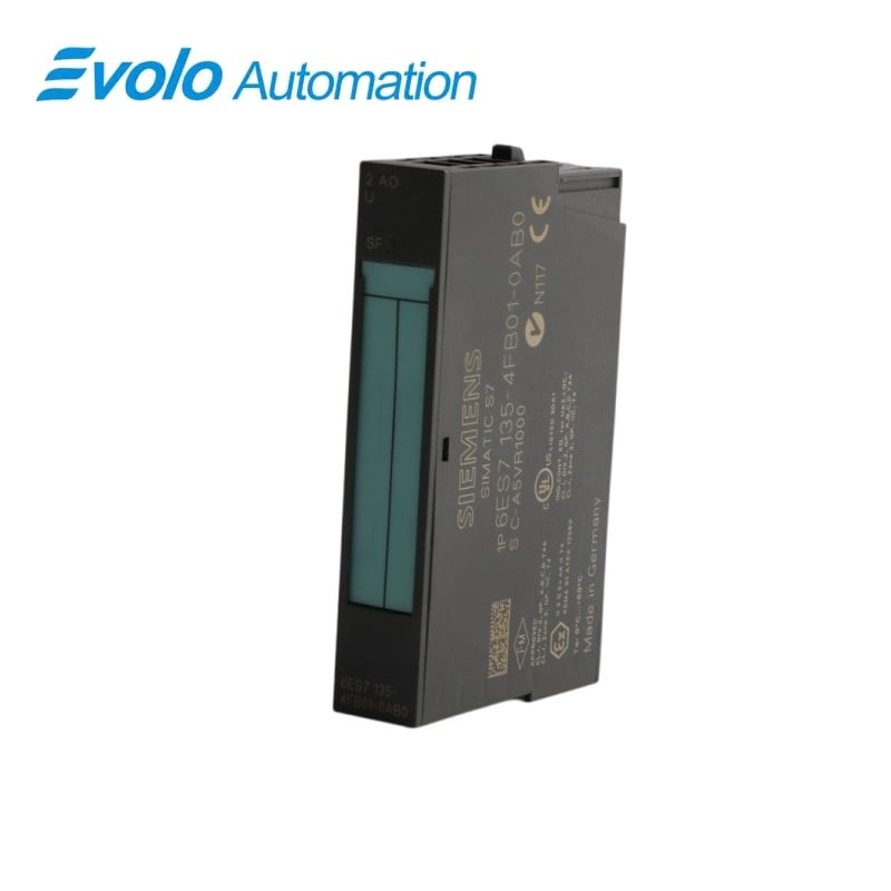
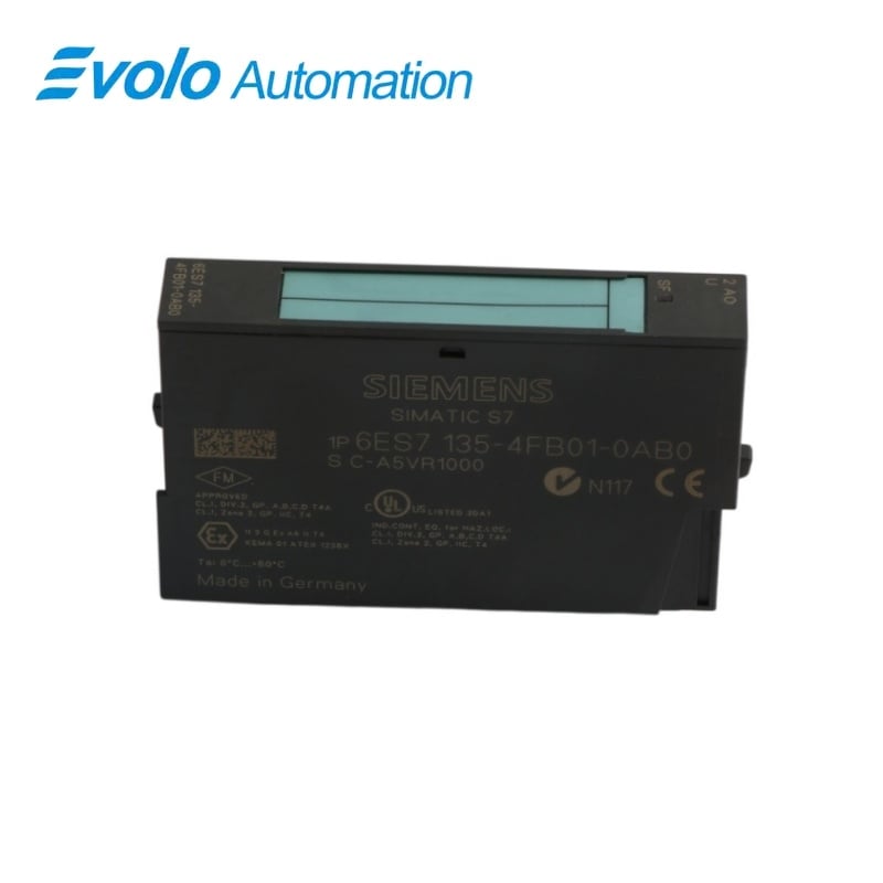
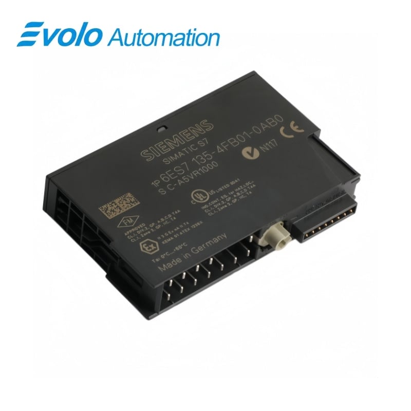
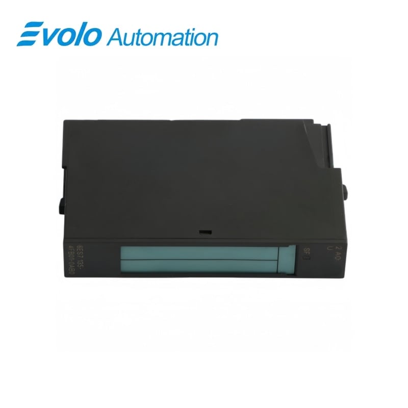
Siemens 6ES7135-4FB01-0AB0 ET 200S Voltage Analog Output Module
Manufacturer: Siemens
Condition: Brand New
Lead Time: In Stock
Origin: Germany
Warranty: 12 Months
Email: [email protected]
whatsApp: +86-18150117685
- Overview
- Hot Selling Models
- Recommended Products
Overview
- Choose ±10 V or 1–5 V to match the receiving equipment.
- Keep the receiving impedance at or above 1 kΩ and capacitive load at or below 1 µF.
- Choose two- or four-wire wiring to suit the actuator circuit.
- Set substitute values within the rated output range during engineering.
6ES7135-4FB01-0AB0 ET 200S Voltage Analog Output Module
Two-channel analog voltage output module with ±10 V and 1–5 V ranges, selectable substitute values and SF fault indication.
At a Glance
| Brand | Siemens |
|---|---|
| Model | 6ES7135-4FB01-0AB0 |
| Product Type | 2 AO U electronics module |
| Core Function | Generation of analog voltage setpoints |
| Application | ET 200S actuator and drive reference circuits |
Selectable voltage setpoints
Configure either ±10 V with 13 bits plus sign or 1–5 V with 12-bit resolution.
Actuator wiring options
Use two-wire voltage output without line-resistance compensation or a four-wire connection.
Fault and substitute-value handling
Short-circuit diagnostics and configurable substitute values support controlled fault response.
Product Overview
6ES7135-4FB01-0AB0 generates two analog voltage setpoints from an ET 200S station for compatible receiving circuits.
Two-wire actuator connections are available without line-resistance compensation, while four-wire connections can also be used; the receiving load must remain within the specified impedance and capacitance limits.
Key Functions
Selectable voltage setpoints
Configure either ±10 V with 13 bits plus sign or 1–5 V with 12-bit resolution.
Actuator wiring options
Use two-wire voltage output without line-resistance compensation or a four-wire connection.
Fault and substitute-value handling
Short-circuit diagnostics and configurable substitute values support controlled fault response.
Official Specifications
| Load Supply | 24 V DC from the power module |
|---|---|
| Maximum Supply Consumption | 130 mA from L+ without load; 10 mA from the 3.3 V backplane |
| Output Address Space | 4 bytes maximum |
| Voltage Ranges | −10 to +10 V and 1–5 V |
| Output Resolution | 13 bits plus sign at ±10 V; 12 bits at 1–5 V |
| Maximum Output Cycle Time | 1.5 ms |
| Minimum Load Impedance | 1 kΩ |
| Maximum Capacitive Load | 1 µF |
| Maximum Short-Circuit Current | 25 mA |
| Settling Time | 0.1 ms resistive; 0.5 ms capacitive or inductive |
| Voltage Error Limits | ±0.2% at 25 °C; ±0.4% across the operating temperature range |
| Maximum Shielded Cable | 200 m |
| Isolation Test Voltage | 500 V DC |
| Dimensions and Approximate Weight | 15 × 81 × 52 mm; 40 g |
Frequently Asked Questions
Can 6ES7135-4FB01-0AB0 supply a 4–20 mA current loop?
The module provides voltage outputs in the ±10 V and 1–5 V ranges.
Can I connect a 500 Ω receiving input to 6ES7135-4FB01-0AB0?
The minimum load impedance is 1 kΩ, so a 500 Ω input is below the permitted load impedance.
Can I use four-wire actuator wiring with 6ES7135-4FB01-0AB0?
Four-wire voltage-output connections are supported alongside two-wire connections without line-resistance compensation.
How should I limit cable capacitance for 6ES7135-4FB01-0AB0?
The total capacitive load must remain at or below 1 µF.
Does 6ES7135-4FB01-0AB0 detect a short circuit on an output?
Short-circuit diagnostics are available and the output short-circuit current is limited to a maximum of 25 mA.
Can 6ES7135-4FB01-0AB0 apply a configured value during a fault?
Configurable substitute values are available within the selected output range.
Are the two outputs on 6ES7135-4FB01-0AB0 galvanically separated?
The outputs are not isolated from one another, but they are isolated from the backplane bus and the L+ load supply.