EN




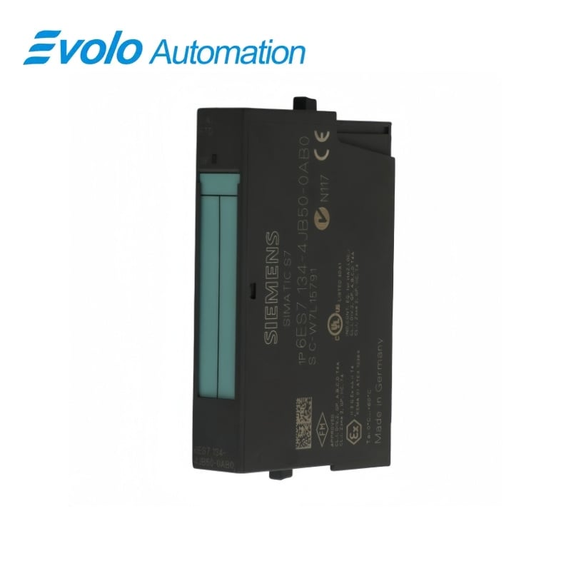
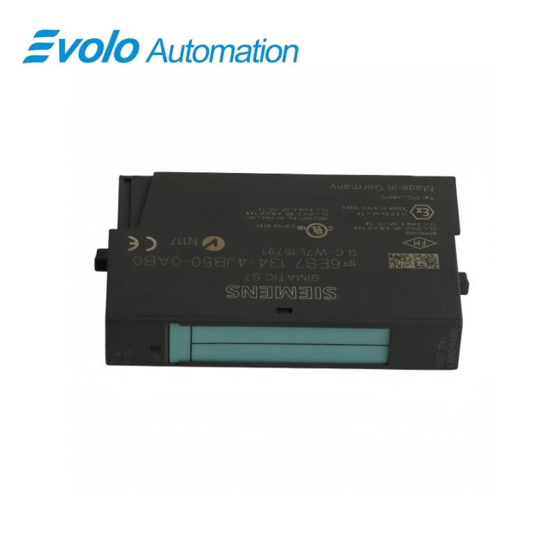
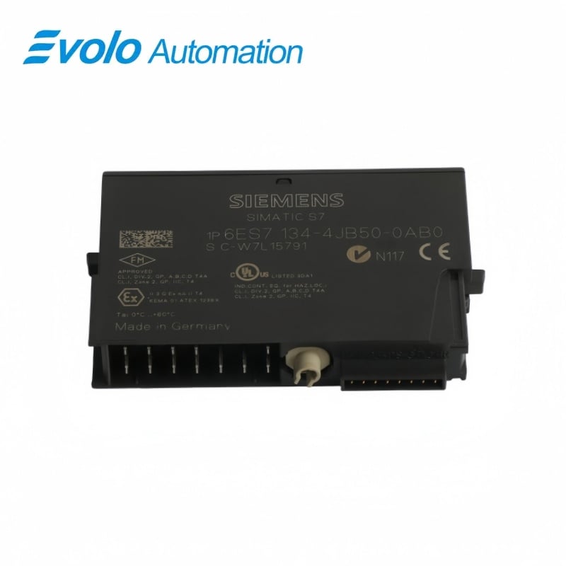
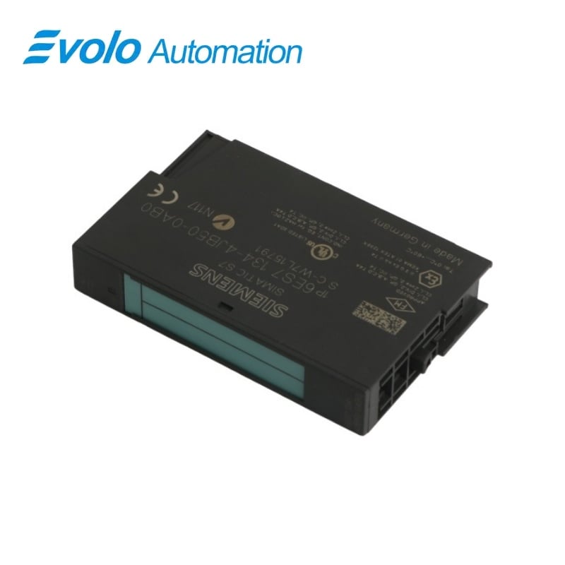
Siemens 6ES7134-4JB50-0AB0 SIMATIC ET 200S Two-Channel RTD Standard Module
Manufacturer: Siemens
Condition: Brand New
Lead Time: In Stock
Origin: Germany
Warranty: 12 Months
Email: [email protected]
whatsApp: +86-18150117685
- Overview
- Hot Selling Models
- Recommended Products
Overview
- Match Pt100 or Ni100 and the selected resistance range.
- Check the terminal module and sensor lead arrangement.
- Allow for measured lead resistance with two-wire or three-wire wiring.
- Select 50/60 Hz integration and the required smoothing level.
- Keep shielded sensor cables within 200 m.
6ES7134-4JB50-0AB0 SIMATIC ET 200S Two-Channel RTD Standard Module
A two-channel RTD module for Pt100, Ni100 and 150/300/600 Ω measurement with selectable integration and digital smoothing.
At a Glance
| Brand | Siemens |
|---|---|
| Model | 6ES7134-4JB50-0AB0 |
| Product Type | RTD analog electronic module |
| Core Function | Measuring temperature and resistance |
| Application | ET 200S distributed I/O |
Direct RTD measurement
Pt100 and Ni100 curves can be linearized in the module.
Selectable filtering
50/60 Hz integration and four smoothing settings adapt the measurement response.
Four-wire acquisition
Four-wire connections separate the measurement leads from the excitation-current path.
Product Overview
6ES7134-4JB50-0AB0 measures two RTD or resistance channels in a 15 mm ET 200S electronic module. Pt100 and Ni100 temperature characteristics are supported together with 150 Ω, 300 Ω and 600 Ω resistance ranges.
The integrative converter provides selectable interference-frequency suppression and digital smoothing. The inputs are isolated from the backplane bus and load supply, while both measurement channels share a potential group.
Key Functions
Linearize RTD signals
Configurable Pt100 and Ni100 characteristics convert resistance into temperature values.
Filter measurement noise
50/60 Hz integration and four digital-smoothing levels adapt the response.
Report measurement faults
A red SF group-error LED and readable diagnostics support fault checks.
Official Specifications
| Input channels | 2 |
|---|---|
| RTD characteristics | Pt100 and Ni100, with parameterizable linearization |
| Resistance measurement ranges | 150 Ω, 300 Ω or 600 Ω |
| Minimum measurement-input resistance | 2 MΩ |
| Rated load supply | 24 V DC from the power module |
| RTD excitation current | Approximately 1.5 mA, short-circuit protected |
| Maximum load-supply current | 30 mA |
| Typical power dissipation | 0.6 W |
| Maximum shielded cable length | 200 m |
| Parameter-data length | 4 bytes |
| Resolution including overrange | Pt100/Ni100: 15 bit plus sign; 150 Ω: 14 bit; 300/600 Ω: 15 bit |
| Integration time | 16.7 ms at 60 Hz rejection; 20 ms at 50 Hz rejection |
| Per-channel conversion time | 110 ms at 60 Hz; 130 ms at 50 Hz |
| Digital-smoothing time constants | 1, 4, 64 or 128 times the module cycle time |
| Electrical isolation | Channels isolated from backplane and L+; no isolation between channels |
| Permitted potential difference to central grounding point | 75 V DC / 60 V AC from MANA |
| Insulation test voltage | 500 V DC |
| Error limits referenced to input range | Operational ±0.6%; basic at 25 °C ±0.4% |
| Dimensions | 15 × 81 × 52 mm (W × H × D), total assembly depends on terminal module |
| Approximate weight | 40 g |
Frequently Asked Questions
Which RTD characteristic should I configure on 6ES7134-4JB50-0AB0?
Select the Pt100 or Ni100 characteristic to match the connected sensor.
Do two-wire or three-wire connections to 6ES7134-4JB50-0AB0 eliminate lead-resistance error?
The line resistances are included in the measurement with two-wire and three-wire connections.
How does the mains-rejection setting affect conversion on 6ES7134-4JB50-0AB0?
Per-channel conversion takes 110 ms at 60 Hz rejection or 130 ms at 50 Hz rejection.
How can I smooth a fluctuating value from 6ES7134-4JB50-0AB0?
Choose one of the four digital-filter settings with time constants of 1, 4, 64 or 128 module cycle times.
Are the two measurement channels of 6ES7134-4JB50-0AB0 isolated from each other?
They share a potential group while remaining isolated from the backplane bus and load supply.
What is the shielded sensor-cable limit for 6ES7134-4JB50-0AB0?
The permitted shielded cable length is up to 200 m.
How can I identify a group fault on 6ES7134-4JB50-0AB0?
The red SF LED indicates a group error and diagnostic information can be read from the module.