EN




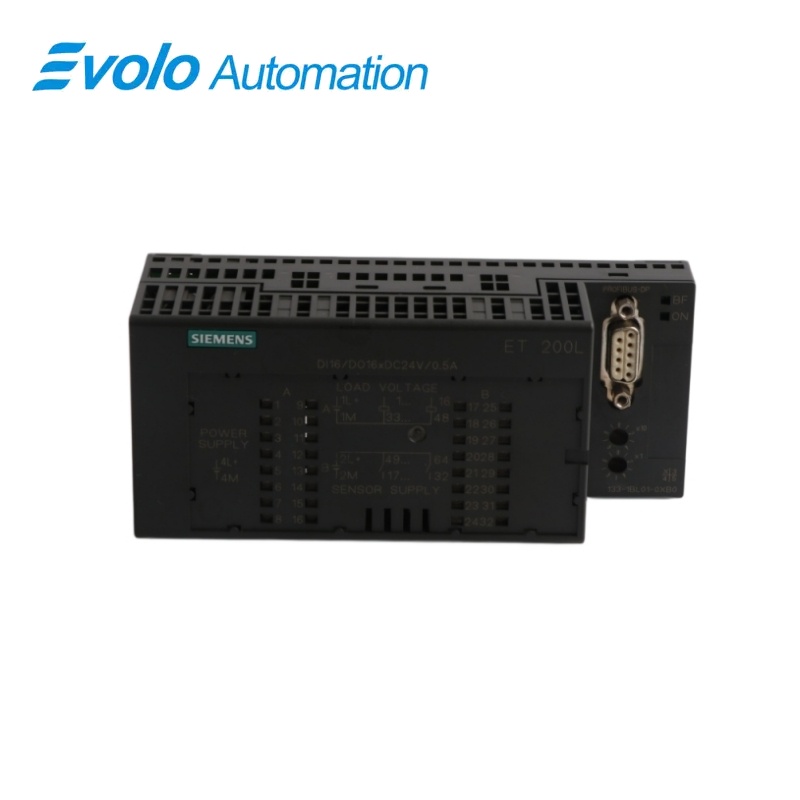
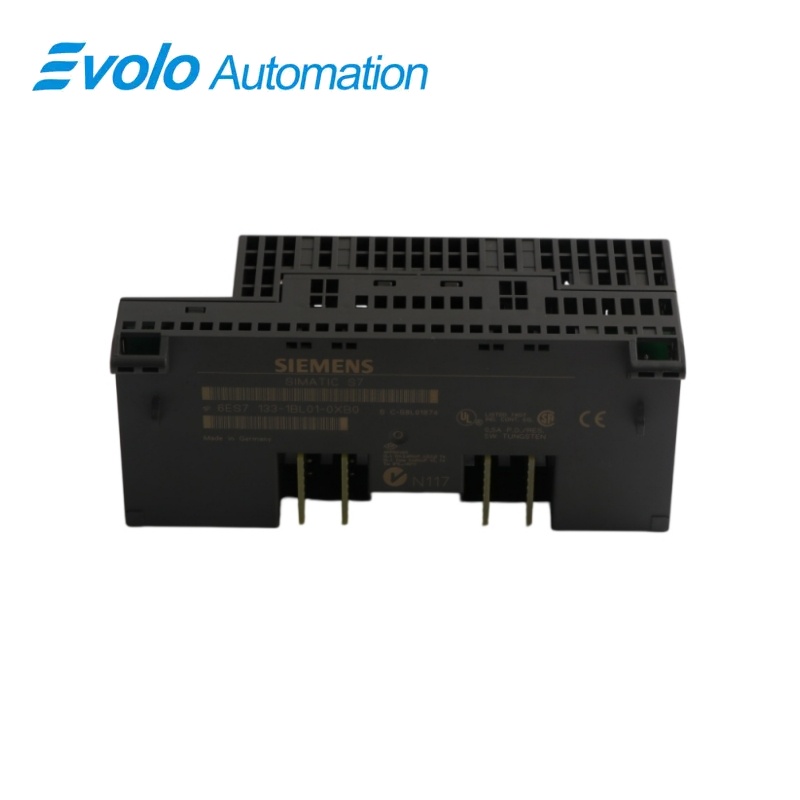
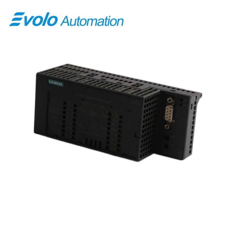
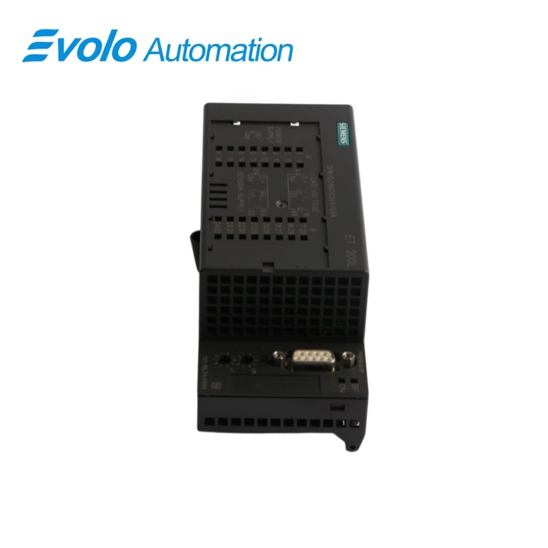
Siemens SIMATIC ET 200L 6ES7133-1BL01-0XB0 16 DI/16 DO Electronic Module
Manufacturer: Siemens
Condition: Brand New
Lead Time: In Stock
Origin: Germany
Warranty: 12 Months
Email: [email protected]
whatsApp: +86-18150117685
- Overview
- Hot Selling Models
- Recommended Products
Overview
- Use the module only in a SIMATIC ET 200L station; do not substitute the ET 200L-SC version.
- Match the TB 32L terminal block: screw-terminal 6ES7193-1CL00-0XA0 or spring-terminal 6ES7193-1CL10-0XA0.
- Confirm the 24 V DC electronics supply at 4L+ and 5L+ and the load supplies at 1L+, 2L+ and 3L+.
- Preserve the installed terminal assignment and separate load-group wiring.
- Verify the PROFIBUS address, configured transmission rate and station entry in the controller project.
- For 45.45 kbaud, use an updated device master file or STEP 7 V4.02 release K4.02.6 or later.
- Check sensor leakage current, actuator type, per-channel current and aggregate output-current derating.
- Siemens lists the exact article as deleted without replacement, so an exchange must be exact rather than assumed equivalent.
Siemens · SIMATIC DP ET 200L
6ES7133-1BL01-0XB0 L 16 DI/16 DO DC 24 V/0.5 A Electronics Block
Siemens 6ES7133-1BL01-0XB0 is a SIMATIC DP ET 200L mixed digital I/O electronics block with 16 inputs and 16 transistor outputs for 24 V DC field signals and 0.5 A loads over PROFIBUS-DP.
At a Glance
| Brand | Siemens |
|---|---|
| Model | 6ES7133-1BL01-0XB0 |
| Product Type | Mixed Digital Input and Output Electronic Module |
| Core Function | Combines decentralized field-signal acquisition and 24 V DC load switching in one ET 200L block |
| Application or Compatible Series | SIMATIC ET 200L distributed I/O stations |
Exact Identification
Match the full BL01 article number and the ET 200L mixed-input-and-output execution before replacement.
Field Wiring
Confirm the 24 V DC sensor and load circuits, TB 32L terminal block and separate load-group wiring.
Bus and Load Setup
Preserve the PROFIBUS address and transmission rate while checking aggregate output-current derating.
Product Overview
Siemens 6ES7133-1BL01-0XB0 is a SIMATIC DP ET 200L mixed digital I/O electronics block with 16 inputs and 16 transistor outputs for 24 V DC field signals and 0.5 A loads over PROFIBUS-DP.
Acquires 16 digital input signals and switches 16 transistor-output loads in one decentralized electronics block. Uses FREEZE and SYNC functions for coordinated process-data handling on the distributed-I/O bus. Provides electronic short-circuit response and status indication for 24 V DC field-load switching.
Key Functions
Mixed Field-Signal Handling
Acquires 16 digital input signals and switches 16 transistor-output loads in one decentralized electronics block.
Synchronized PROFIBUS-DP Exchange
Uses FREEZE and SYNC functions for coordinated process-data handling on the distributed-I/O bus.
Protected Output Operation
Provides electronic short-circuit response and status indication for 24 V DC field-load switching.
Official Specifications
| Physical Dimensions | 145 × 60 × 60.5 mm |
|---|---|
| PROFIBUS Transmission Rates | 9.6, 19.2, 45.45, 93.75, 187.5, 500 and 1500 kbaud |
| Connected Cable Length | Maximum 600 m unshielded; maximum 1000 m shielded |
| Bus Synchronization Functions | FREEZE and SYNC |
| Electronics Supply | 24 V DC at 4L+ and 5L+, with reverse-polarity protection |
| Power-Failure Withstand Time | At least 20 ms |
| Load-Circuit Supply | 24 V DC at 1L+, 2L+ and 3L+ |
| Simultaneously Driven Inputs | Maximum 16 |
| Aggregate Output Current per Byte | Horizontal mounting: 4 A to 30 °C, 3 A to 40 °C and 2 A to 60 °C; other positions: 2 A to 40 °C |
| Electrical Isolation | No isolation between channels; isolation between channels and PROFIBUS-DP, tested at 500 V DC |
| No-Load Current Consumption | Maximum 70 mA from L4+ and L5+, and maximum 50 mA per load group from L1+ or L2+ and L3+ |
| Typical Module Power Loss | 5 W |
| Status and Diagnostic Indication | Green LED per channel, red BF LED for bus monitoring and green ON LED for electronics-supply monitoring; no interrupts |
| Input Signal Thresholds | Signal 1: 13 to 30 V; signal 0: −30 to 5 V |
| Input Current and Delay | Typically 5 mA at 24 V; 2.0 to 4.5 ms for both signal transitions |
| Input Characteristic and Sensor Limit | IEC 1131-2 Type 1; two-wire BERO connection permitted with maximum 1.5 mA closed-circuit current |
| Output Electrical Values | Signal 1 voltage at least the associated load supply minus 3 V; output-current range 1 mA to 0.5 A; signal 0 residual current maximum 1 mA |
| Output Switching Delay | Maximum 50 µs from 1 to 0 and maximum 200 µs from 0 to 1 with resistive load |
| Load Resistance and Lamp Rating | 41 Ω to 28 kΩ; lamp load maximum 5 W |
| Switching and Protection Limits | Resistive load maximum 100 Hz, IEC 947-5-1 DC-13 inductive load maximum 0.5 Hz and lamp load maximum 8 Hz; short-circuit response approximately 0.7 to 1.5 A |
Frequently Asked Questions
Can I install 6ES7133-1BL01-0XB0 in a SIMATIC ET 200L station?
Yes, the electronics block is intended for an ET 200L distributed I/O station operating on PROFIBUS-DP.
Which sensors can I connect to 6ES7133-1BL01-0XB0?
You can connect mechanical switches and compatible two-wire proximity switches whose closed-circuit current does not exceed 1.5 mA.
Which field loads can 6ES7133-1BL01-0XB0 switch?
It is intended for 24 V DC solenoids, DC contactors and indicator lamps within the 0.5 A channel rating and applicable aggregate-current limits.
Which input levels should I design for when wiring 6ES7133-1BL01-0XB0?
Use 13 to 30 V for a definite signal 1 and −30 to 5 V for a definite signal 0.
How should I derate the outputs of 6ES7133-1BL01-0XB0?
Keep each output byte within 4 A at 30 °C, 3 A at 40 °C or 2 A at 60 °C for horizontal mounting, and within 2 A at 40 °C for other positions.
Are the channels of 6ES7133-1BL01-0XB0 electrically isolated from each other?
The channels are not mutually isolated, but they are isolated from the PROFIBUS-DP side and tested at 500 V DC.
What should I verify before replacing 6ES7133-1BL01-0XB0?
Match the full suffix, TB 32L terminal block, supply-group wiring, PROFIBUS address, baud rate and installed project configuration before exchanging the block.