EN




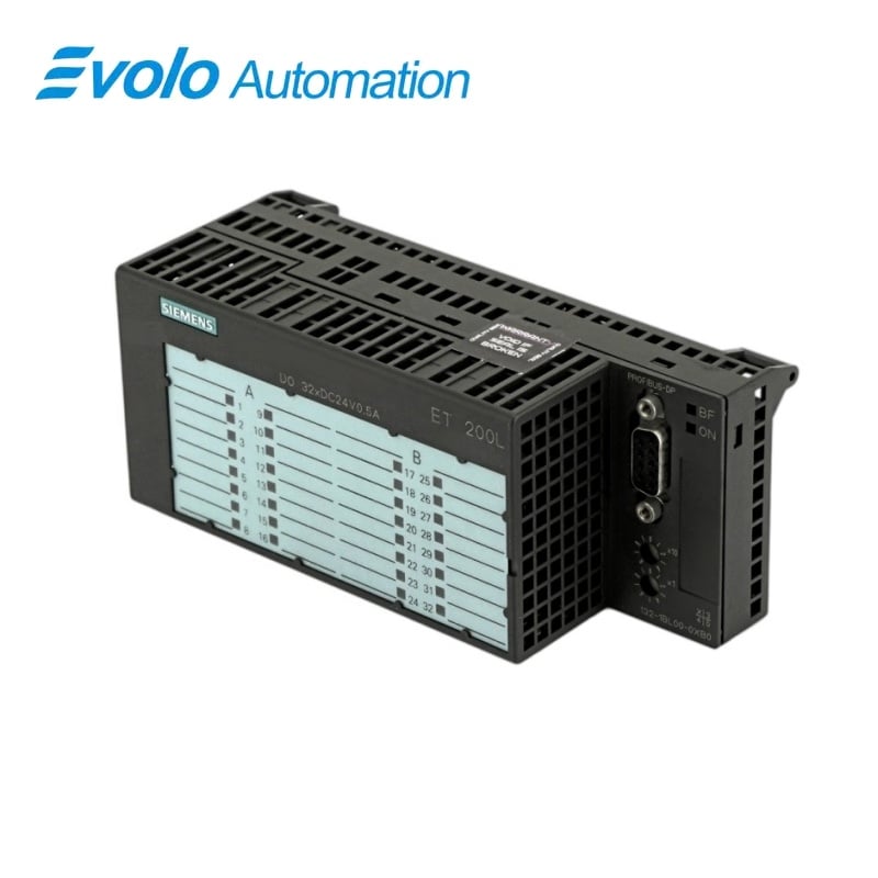
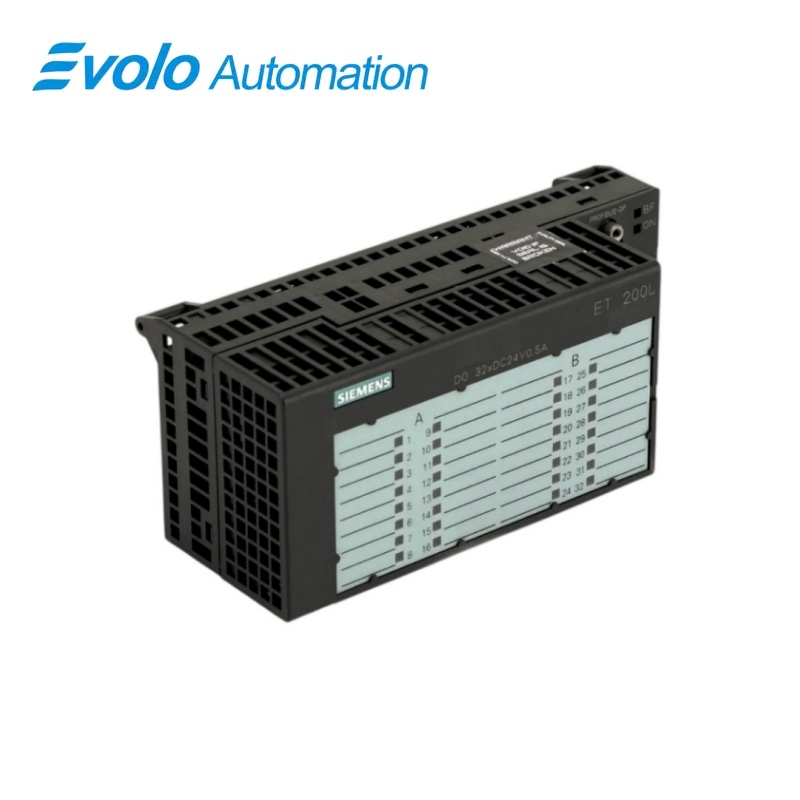
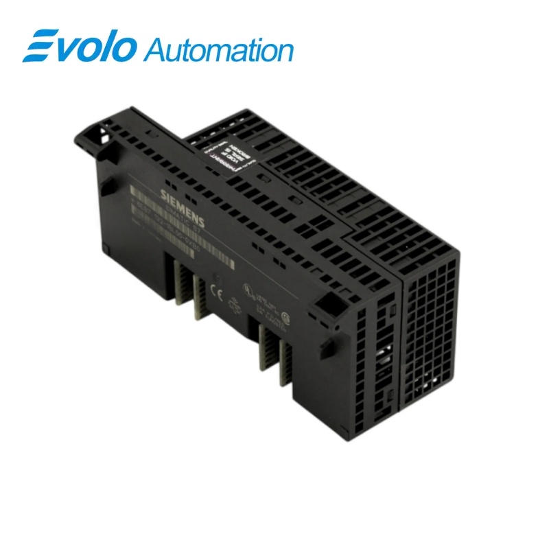
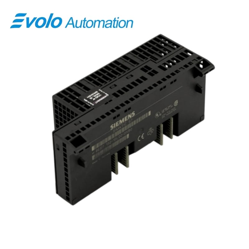
Siemens SIMATIC ET 200L 6ES7132-1BL00-0XB0 32-Output Electronics Block
Manufacturer: Siemens
Condition: Brand New
Lead Time: In Stock
Origin: Germany
Warranty: 12 Months
Email: [email protected]
whatsApp: +86-18150117685
- Overview
- Hot Selling Models
- Recommended Products
Overview
- Select TB 32L 6ES7193-1CL00-0XA0 or 6ES7193-1CL10-0XA0.
- Provide separate 24 V DC electronics and load-supply wiring according to the ET 200L connection scheme.
- Configure the station as a PROFIBUS-DP device at one of the verified transmission rates.
- Apply the per-byte aggregate-current derating for temperature and mounting position.
- Keep inductive DC13 switching at or below 0.5 Hz.
- If increasing current by parallel connection, use outputs from the same group only.
- Keep unshielded PROFIBUS cable within 600 m or shielded cable within 1000 m.
Siemens · SIMATIC ET 200L
6ES7132-1BL00-0XB0 L 32 DO DC 24 V/0.5 A Electronics Block
Siemens 6ES7132-1BL00-0XB0 is an ET 200L output electronics block with 32 DC outputs divided into two groups of 16 for solenoid valves, DC contactors and indicator lamps.
At a Glance
| Brand | Siemens |
|---|---|
| Model | 6ES7132-1BL00-0XB0 |
| Product Type | Digital Output Electronics Block |
| Core Function | Converts controller commands into grouped discrete field switching |
| Application or Compatible Series | SIMATIC ET 200L distributed I/O |
Terminal Block Match
Use the TB 32L screw-terminal version 6ES7193-1CL00-0XA0 or spring-terminal version 6ES7193-1CL10-0XA0.
Load and Supply Planning
Plan the three load-supply connections and observe the aggregate-current limit for every output byte.
Switching-Duty Check
Confirm that each resistive, inductive or lamp load remains within the documented current and switching-frequency limits.
Product Overview
Siemens 6ES7132-1BL00-0XB0 is an ET 200L output electronics block with 32 DC outputs divided into two groups of 16 for solenoid valves, DC contactors and indicator lamps.
The block switches 32 DC field outputs arranged in two groups of 16. The outputs drive solenoids, DC contactors and indicator lamps within the documented electrical limits. Green channel LEDs, a red bus-fault indicator and an electronics-supply indicator support commissioning.
Key Functions
High-Density Output Control
The block switches 32 DC field outputs arranged in two groups of 16.
Industrial Load Switching
The outputs drive solenoids, DC contactors and indicator lamps within the documented electrical limits.
Local Status and Bus Indication
Green channel LEDs, a red bus-fault indicator and an electronics-supply indicator support commissioning.
Official Specifications
| Output Arrangement | 32 outputs in two groups of 16 |
|---|---|
| Electronics Supply | 24 V DC with reverse-polarity protection |
| Power-Failure Withstand Time | At least 20 ms |
| Rated Load Voltage | 24 V DC |
| Output Current | 1 mA to 0.5 A for signal 1; 1 mA maximum residual current for signal 0 |
| Output Delay with Resistive Load | 50 µs maximum from 1 to 0; 200 µs maximum from 0 to 1 |
| Load Resistance Range | 41 Ω to 28 kΩ |
| Maximum Lamp Load | 5 W |
| Switching Frequencies | 100 Hz resistive, 0.5 Hz inductive to IEC 947-5-1 DC13, and 8 Hz lamp |
| Short-Circuit Response Threshold | Typically 0.7 A to 1.5 A |
| Inductive Interruption Clamp | Typically group supply minus 55 V |
| Aggregate Current per Output Byte | Horizontal: 4 A to 30 °C, 3 A to 40 °C, 2 A to 60 °C; other positions: 2 A to 40 °C |
| Electronics-Supply Current | 70 mA maximum from L4+ and L5+ |
| No-Load Current per Load Group | 50 mA maximum |
| Typical Module Power Loss | 5 W |
| Potential Isolation | No isolation between channels; isolation from PROFIBUS-DP tested at 500 V DC |
| Bus Protocol and Rates | PROFIBUS-DP at 9.6, 19.2, 45.45, 93.75, 187.5, 500 or 1500 kbaud |
| PROFIBUS Cable Length | 600 m maximum unshielded; 1000 m maximum shielded |
| Dimensions | 145 × 60 × 60.5 mm |
| Approximate Weight | 150 g |
Frequently Asked Questions
Which terminal blocks fit 6ES7132-1BL00-0XB0?
The block fits TB 32L 6ES7193-1CL00-0XA0 with screw terminals or 6ES7193-1CL10-0XA0 with spring terminals.
How are the outputs grouped on 6ES7132-1BL00-0XB0?
The 32 outputs are divided into two groups of 16.
Which field loads are appropriate for 6ES7132-1BL00-0XB0?
Suitable loads include solenoids, DC contactors and indicator lamps within the stated electrical limits.
How does mounting position affect 6ES7132-1BL00-0XB0 output loading?
Horizontal mounting permits up to 4 A per byte at 30 °C, while other positions are limited to 2 A per byte at 40 °C.
What is the inductive-load switching limit for 6ES7132-1BL00-0XB0?
The maximum switching frequency for an IEC 947-5-1 DC13 inductive load is 0.5 Hz.
Can two outputs of 6ES7132-1BL00-0XB0 be wired in parallel?
Parallel connection is permitted only for current uprating with outputs from the same group, while redundant load control is not permitted.
Which indicators help troubleshoot 6ES7132-1BL00-0XB0?
Green channel LEDs show output status, the red BF LED reports a PROFIBUS fault and the green ON LED confirms electronics power.