EN




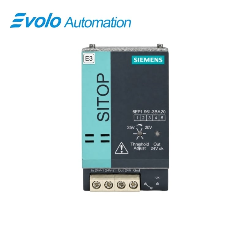
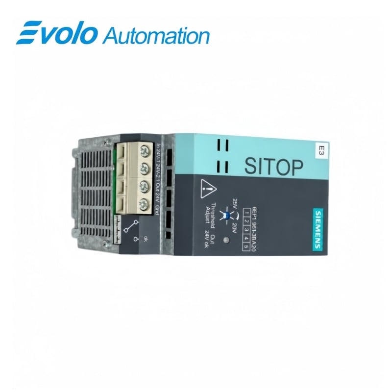
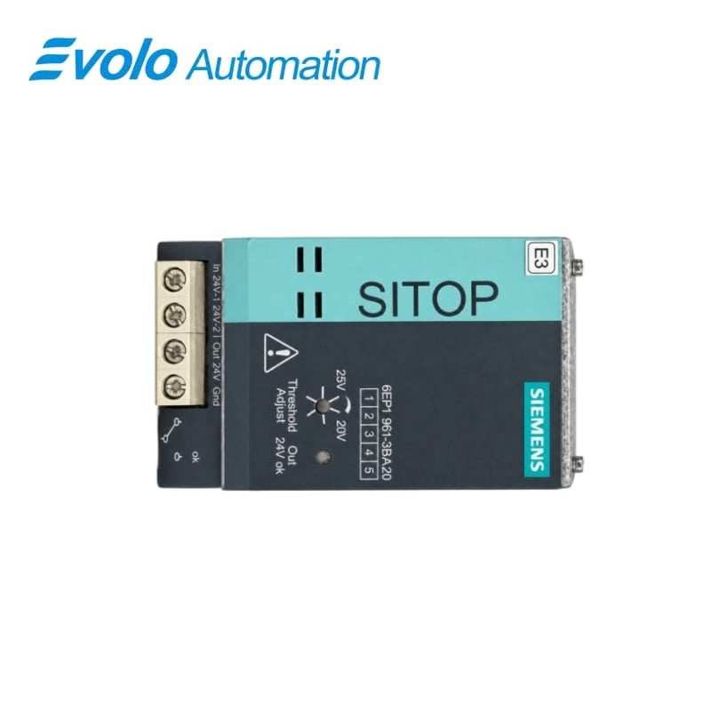
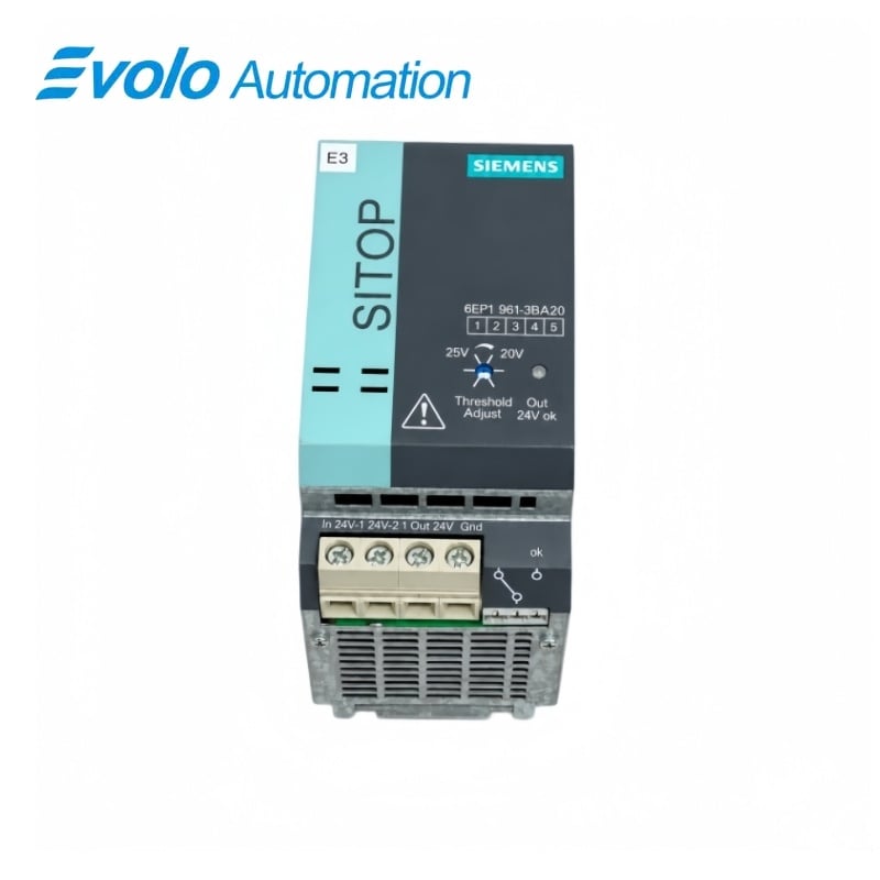
Siemens 6EP1961-3BA20 SITOP Modular Redundancy Module
Manufacturer: Siemens
Condition: Brand New
Lead Time: In Stock
Origin: Germany
Warranty: 12 Months
Email: [email protected]
whatsApp: +86-18150117685
- Overview
- Hot Selling Models
- Recommended Products
Overview
- Connect each supply positive to its assigned input and both negatives to the Gnd reference.
- Use two modules for redundant 30 A or 40 A supply arrangements.
- Mount on a 35 × 15 mm or 35 × 7.5 mm DIN rail with terminals downward.
- Leave 50 mm clearance above and below.
- For Ex applications, provide an installation with IP54 protection.
- Set the monitoring threshold to suit the intended 24 V supply.
6EP1961-3BA20 SITOP Modular Redundancy Module
A diode redundancy module for stabilized 24 V supplies, with adjustable input-voltage monitoring and a floating changeover contact.
At a Glance
| Brand | Siemens |
|---|---|
| Model | 6EP1961-3BA20 |
| Product Type | Power-supply redundancy module |
| Core Function | Decouples two supplies into a common load feed |
| Application | Redundant industrial DC power distribution |
Redundant supply path
A remaining supply feeds the load if the other supply fails.
Voltage supervision
A potentiometer sets the monitoring threshold from 20 to 25 V.
Cabinet integration
DIN-rail mounting and natural cooling support panel installation.
Product Overview
6EP1961-3BA20 combines two stabilized 24 V power supplies through diode decoupling to provide a redundant load supply.
An LED indication and floating relay contact report the input-voltage condition, while the separate In 24V-1 and In 24V-2 terminals connect the two source feeds.
Key Functions
Diode-decoupled load feed
The common output supplies the load from either connected source, with an approximate 0.5 V diode voltage drop.
Adjustable failure indication
The voltage-monitoring threshold can be adjusted over 20–25 V, with green and red status indications and a floating changeover contact.
Higher-current redundant arrangements
Two modules are required when using two supplies rated 30 A or 40 A, with one module assigned to each supply and its two inputs interconnected.
Official Specifications
| Rated input voltage | 24 V DC |
|---|---|
| Operating input range | 22–28.8 V DC |
| Output voltage | Input voltage minus approximately 0.5 V |
| Output current range | 0–40 A total |
| Monitoring threshold adjustment | 20 V ±0.5 V to 25 V ±0.5 V |
| Signaling contact | Floating changeover contact, 6 A at 240 V AC |
| Status indications | Green: both inputs above threshold; red: at least one input below threshold |
| Operating temperature | 0–60 °C |
| Storage and transport temperature | −25 to +85 °C |
| Climatic category | 3K3 to EN 60721-3, without condensation |
| Cooling | Natural air cooling |
| Degree of protection | IP20 to IEC 529 |
| Electrical safety | Class I to IEC 536; SELV to EN 60950 |
| Power terminal conductor range | 0.33–10 mm² |
| Power terminal tightening torque | 1.2 N·m |
| Signaling terminal conductor range | 0.5–2.5 mm² |
| Signaling terminal tightening torque | 0.5–0.6 N·m |
| Net weight | 1.0 kg |
Frequently Asked Questions
Can one 6EP1961-3BA20 connect two 20 A power supplies?
One module can form the redundant arrangement for two stabilized 24 V supplies rated up to 20 A each.
How should two 40 A supplies be connected through 6EP1961-3BA20?
Use two redundancy modules, assign one to each supply and bridge the two input terminals on each module.
Why is the voltage after 6EP1961-3BA20 lower than the supply setting?
The diode path reduces the output voltage by approximately 0.5 V relative to the input.
How do I set the alarm point on 6EP1961-3BA20?
Adjust the potentiometer to select an input-voltage threshold between 20 and 25 V.
What does a red LED on 6EP1961-3BA20 mean?
A red indication means that at least one input voltage is below the selected switching threshold.
How much ventilation space does 6EP1961-3BA20 need?
Mount the module vertically with its terminals at the bottom and leave at least 50 mm clear above and below.
How should I size the load cable from 6EP1961-3BA20?
Size the output conductor to carry the maximum combined current of both connected power supplies.