EN




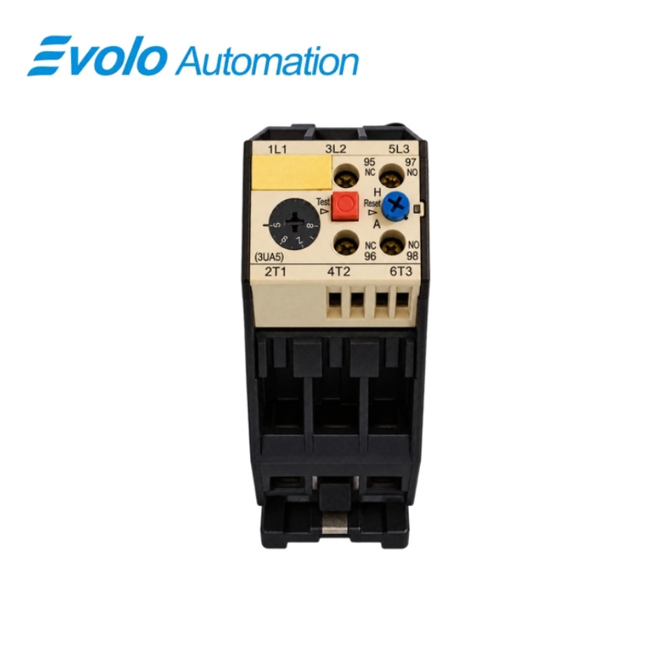
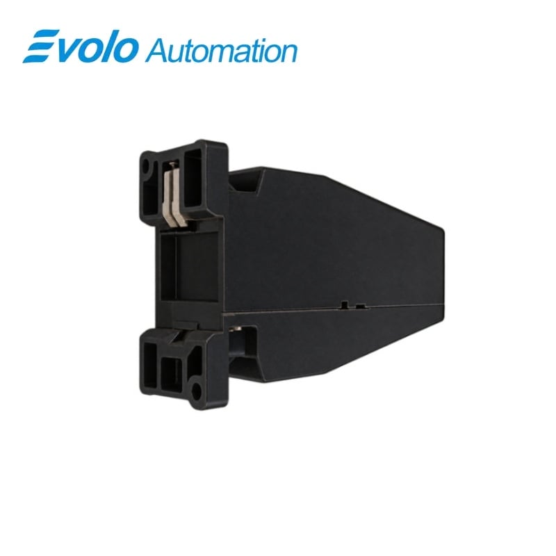
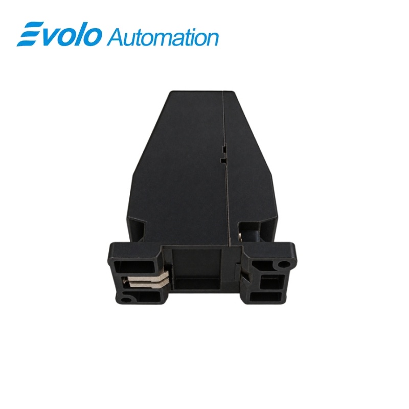
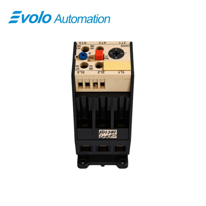
Siemens 3UA59 40-1J 3UA59 Thermal Overload Relay 6.3-10A
Manufacturer: Siemens
Condition: Brand New
Lead Time: In Stock
Origin: Germany
Warranty: 12 Months
Email: [email protected]
whatsApp: +86-18150117685
- Overview
- Hot Selling Models
- Recommended Products
Overview
- Set the adjustment to the actual load rated current within 6.3–10 A.
- Use the compatible manufacturer-certified contactor combination or an approved separate-mounting arrangement.
- Choose H manual or A automatic reset for the machine’s control sequence.
- Use copper conductors within the specified cross-sections and apply the separate main and auxiliary tightening torques.
- Provide coordinated main-circuit short-circuit protection and the specified auxiliary-circuit protection.
- For a single-phase load, connect all three main current paths in series.
3UA59 40-1J 3UA59 Thermal Overload Relay 6.3-10A
A 3UA59 overload relay with a 6.3–10 A setting range, manual or automatic reset, a test button and one normally open plus one normally closed control contact.
At a Glance
| Brand | Siemens |
|---|---|
| Model | 3UA59 40-1J |
| Product Type | Adjustable thermal overload relay |
| Core Function | Motor overload and phase-failure protection |
| Application | Compatible motor-contactor assemblies or separate mounting |
Load-current setting
The 1J range adjusts from 6.3 A to 10 A.
Reset selection
The blue button selects manual H or automatic A reset.
Control-circuit test
The red test button opens the NC contact and closes the NO contact.
Product Overview
3UA59 40-1J is the open-type 3UA59 thermal overload relay with the 40 construction code and 1J current-setting range of 6.3–10 A.
The phase-failure-sensitive relay is ambient-temperature compensated and provides a reset selection, overload simulation using the test button and control contacts for the motor-control circuit.
Key Functions
Set protection to the load current
The adjustment scale is set to the load’s rated current within the 6.3–10 A range of this article.
Choose manual or automatic resetting
The blue reset button makes the relay ready after tripping, with H for manual resetting and A for automatic resetting.
Test the control contacts and read the trip indication
Pressing the red test button opens the NC contact and closes the NO contact, while the green trip pin indicates a trip in manual-reset mode.
Official Specifications
| Adjustable Current Range | 6.3–10 A |
|---|---|
| Main-Circuit Rated Insulation Voltage | 690 V AC |
| Auxiliary-Contact Arrangement | 1 NO + 1 NC |
| Ambient Compensation | Ambient-temperature compensated |
| Reset Modes | H manual and A automatic; supplied in H mode |
| Degree of Protection | IP20; finger-safe to DIN VDE 0106 Part 100 |
| Permissible Ambient Temperature | −25 to +55 °C |
| Main-Conductor Cross-Section | Solid or stranded: 1.5–25 mm²; finely stranded with ferrule: 1–16 mm² |
| Auxiliary-Conductor Cross-Section | Solid: 2 × 0.5–1 or 2 × 1–2.5 mm²; finely stranded with ferrule: 2 × 0.5–1 or 2 × 0.75–2.5 mm² |
| Terminal Screws and Tightening Torque | Main: M5, 2.5–3.0 N·m; auxiliary: M3.5, 0.8–1.4 N·m |
| Auxiliary AC-15 Ratings | 2 A at 24 V; 1.5 A at 60 V; 1.25 A at 125 V; 1.15 A at 230 V; 1.1 A at 400 V; 0.8 A at 690 V |
| Auxiliary DC-13 Ratings | 2 A at 24 V; 0.5 A at 60 V; 0.3 A at 110 V; 0.2 A at 220 V |
| Separate-Mounting Options | 35 mm top-hat rail or bolted mounting on a flat surface |
| Auxiliary Short-Circuit Protection | 6 A NH/NEOZED/DIAZED fuse, 10 A fast DIAZED fuse, or 3 A characteristic-C circuit breaker |
Frequently Asked Questions
How should I set the current dial on 3UA59 40-1J for commissioning?
Set the scale to the load’s rated current within the 6.3–10 A adjustment range.
How do I change 3UA59 40-1J from manual to automatic reset?
Press the blue button and turn it counterclockwise from H to A.
What should happen to the control contacts when I press the red button on 3UA59 40-1J?
The NC contact opens and the NO contact closes to simulate overload tripping.
Why is there no green trip-pin indication when 3UA59 40-1J is set to A?
The protruding green trip indication operates in the H manual-reset setting rather than the A automatic-reset setting.
Can I mount 3UA59 40-1J separately from the contactor?
The separate-mounting arrangement supports a 35 mm top-hat rail or bolted mounting on a flat surface.
What should I do with the three main current paths of 3UA59 40-1J for a single-phase load?
Connect all three main current paths in series for the single-phase load.
What torque should I use when wiring the main and auxiliary terminals of 3UA59 40-1J?
Tighten the M5 main terminals to 2.5–3.0 N·m and the M3.5 auxiliary terminals to 0.8–1.4 N·m.