EN




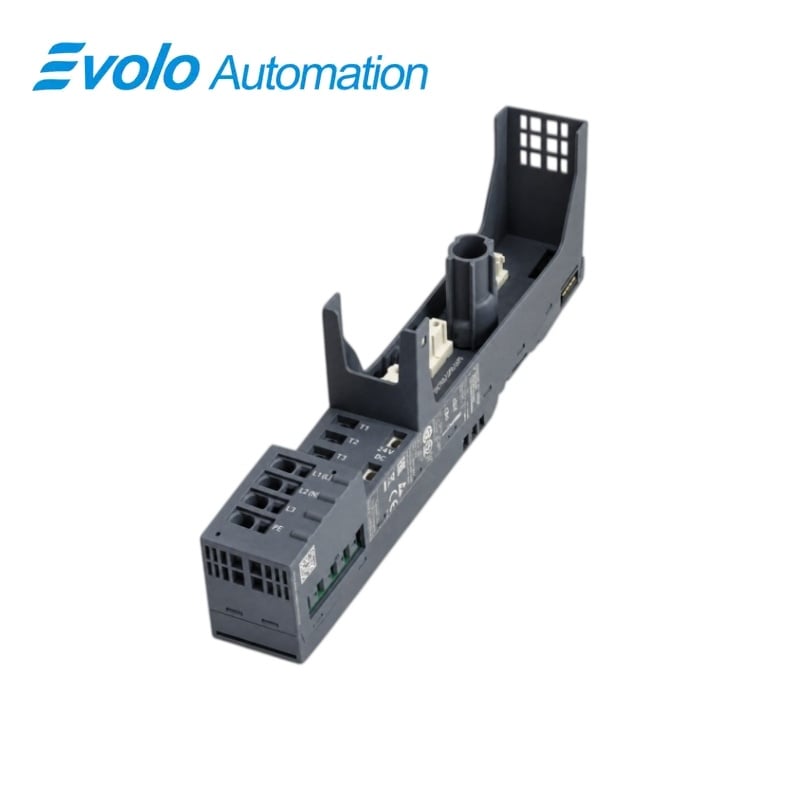
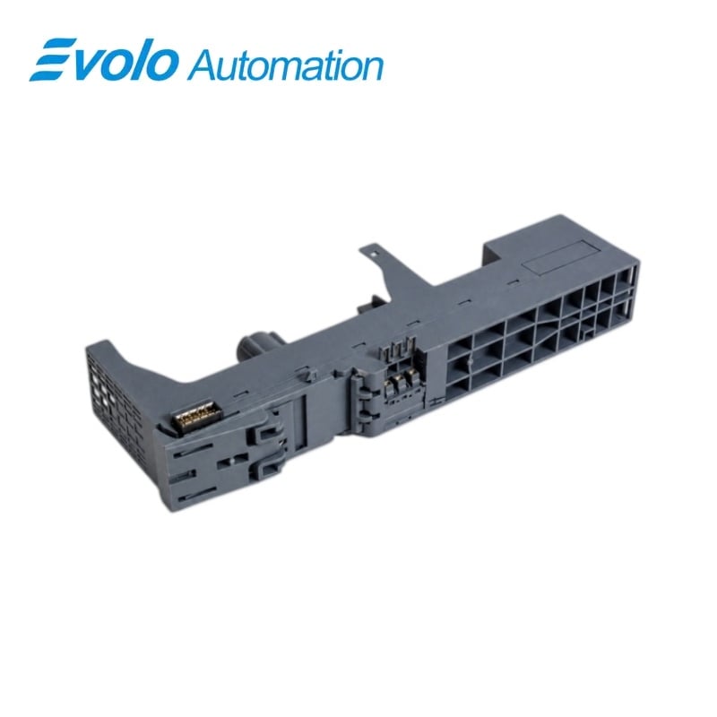
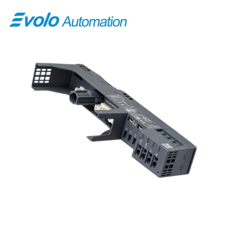
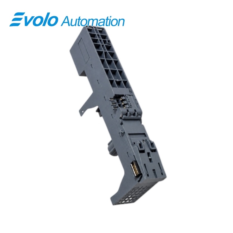
Siemens 3RK1908-0AP00-0AP0 ET 200SP BU30-MS1 Motor Starter BaseUnit
Manufacturer: Siemens
Condition: Brand New
Lead Time: In Stock
Origin: Germany
Warranty: 12 Months
Email: [email protected]
whatsApp: +86-18150117685
- Overview
- Hot Selling Models
- Recommended Products
Overview
- Use this variant when the starter position requires both main-circuit and 24 V DC infeed.
- Match the 500 V motor-starter or 480 V e-Starter voltage limit to the installed starter type.
- Apply the current derating for the chosen orientation and operating temperature.
- Keep the infeed bus cover fitted and provide the required 50 mm upper and lower ventilation space.
3RK1908-0AP00-0AP0 ET 200SP BU30-MS1 Motor Starter BaseUnit
A BU30-MS1 BaseUnit with both 24 V DC and main-circuit infeed, including the infeed bus cover.
At a Glance
| Brand | Siemens |
|---|---|
| Model | 3RK1908-0AP00-0AP0 |
| Product Type | Motor-starter BaseUnit |
| Core Function | Power and control infeed connection |
| Application | ET 200SP motor-starter assemblies |
Combined power and control infeed
The BaseUnit provides main-circuit infeed and 24 V DC supply in one motor-starter position.
Push-in feeder wiring
Spring-loaded terminals connect the main circuit, auxiliary supply and load outgoing wiring without screw-terminal tightening.
Starter-specific installation
The 30 mm-wide DIN-rail base supports the motor-starter assembly and includes the infeed bus cover.
Product Overview
3RK1908-0AP00-0AP0 provides the BaseUnit position with 24 V control and main-circuit infeed for ET 200SP motor starters.
The three-pole power path, push-in terminals and included infeed bus cover form the wiring base beneath the starter, with separate conductor limits for the main infeed, control supply and load outgoing connections.
Key Functions
Combined power and control infeed
The BaseUnit provides main-circuit infeed and 24 V DC supply in one motor-starter position.
Push-in feeder wiring
Spring-loaded terminals connect the main circuit, auxiliary supply and load outgoing wiring without screw-terminal tightening.
Starter-specific installation
The 30 mm-wide DIN-rail base supports the motor-starter assembly and includes the infeed bus cover.
Official Specifications
| Main-circuit poles | 3 poles, AC |
|---|---|
| Starter voltage application | Up to 500 V AC for motor starters; 480 V AC for ET 200SP e-Starter |
| Rated operational current | 32 A at 400 V AC; installation-dependent derating applies |
| Control supply | 24 V DC; permitted 20.4–28.8 V DC |
| Maximum DC supply ampacity | 7 A |
| Insulation and impulse withstand | 500 V rated insulation; 6 kV impulse withstand |
| Pollution degree | 2 |
| Protective separation | Maximum 500 V between main and auxiliary circuits |
| Front protection | IP20; finger-safe |
| Terminal technology | Spring-loaded push-in connections |
| Main-infeed conductors | 1–6 mm²; AWG 18–10 |
| DC-input conductors | 24 V infeed: 0.5–2.5 mm²; AWG 20–12 |
| Load-outgoing conductors | Three-pole load connection: 0.5–2.5 mm²; AWG 20–12 |
| Mounting orientation | Vertical or horizontal, DIN-rail mounting |
| Required ventilation space | 50 mm above and below |
| Operating temperature | −25 to +60 °C; derating applies |
| Storage and transport temperature | −40 to +70 °C |
| Dimensions | 30 × 215 × 75 mm |
| Shock withstand | 6 g for 11 ms |
| Net weight | 0.175 kg |
Frequently Asked Questions
Does 3RK1908-0AP00-0AP0 provide both the main infeed and the 24 V control infeed?
This BaseUnit includes both main-circuit and 24 V DC infeed connections.
Can I use the full 500 V rating of 3RK1908-0AP00-0AP0 with an ET 200SP e-Starter?
The permitted AC supply is 500 V for motor starters but 480 V for the ET 200SP e-Starter.
Does 3RK1908-0AP00-0AP0 add any digital-input channels to the station?
The BaseUnit has zero digital inputs.
Which wire sizes can I use at the main infeed of 3RK1908-0AP00-0AP0?
The main-infeed terminals accept conductors from 1 to 6 mm², corresponding to AWG 18 through 10.
Do the DC-input and load-outgoing terminals on 3RK1908-0AP00-0AP0 use the same conductor range?
Both terminal groups accept conductors from 0.5 to 2.5 mm², corresponding to AWG 20 through 12.
What cooling space should I provide around 3RK1908-0AP00-0AP0?
Maintain 50 mm of free space above and below the BaseUnit assembly.
Can I assume 3RK1908-0AP00-0AP0 carries 32 A at every mounting temperature?
The 32 A rating at 400 V AC is subject to the installation and temperature derating conditions.