EN
EN




- Overview
- Specifications
- Description
- Applications
- FEATURES
- SPECIAL H ANDLING
- REPLACEMENT
- FAQ
- Recommended Products
Overview
Place of Origin: |
Sweden |
Brand Name: |
ABB |
Model Number: |
NTAI06 |
Packaging Details: |
Original new Factory Sealed |
Delivery Time: |
5-7 days |
Payment Terms: |
T/T |
Supply Ability: |
In stock |
Specifications
|
Parameter |
Specification |
|
Model |
NTAI06 |
|
Device Type |
Bailey Infi 90 Analog Input Termination Unit |
|
Dimensions |
96.52 × 236.22 × 218.44 mm (D×H×W) |
|
Weight |
0.635 kg |
|
Power Requirements |
+24 V DC (required for 4–20 mA system-powered inputs) |
|
Mounting |
Installs in NFTP01 Field Termination Panel |
|
Operating Temperature |
0 °C to +70 °C |
|
Humidity |
5–90 % ±5 % up to 55 °C; 5–40 % ±5 % at 70 °C (non-condensing) |
|
Atmospheric Pressure |
Sea level to 3 km |
|
Air Quality |
Non-corrosive environment |
|
EMI/RFI Precautions |
Keep cabinet doors closed; maintain ≥2 m from communication equipment |
|
Cooling Requirements |
No cooling required within specified limits |
|
Certification |
CSA certified for process control equipment in non-hazardous locations |
Description
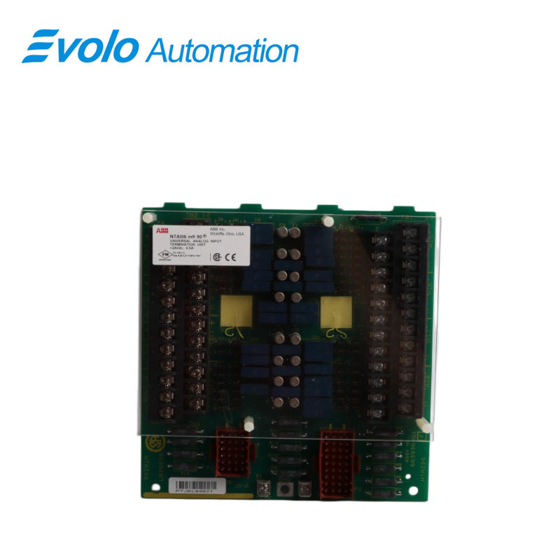
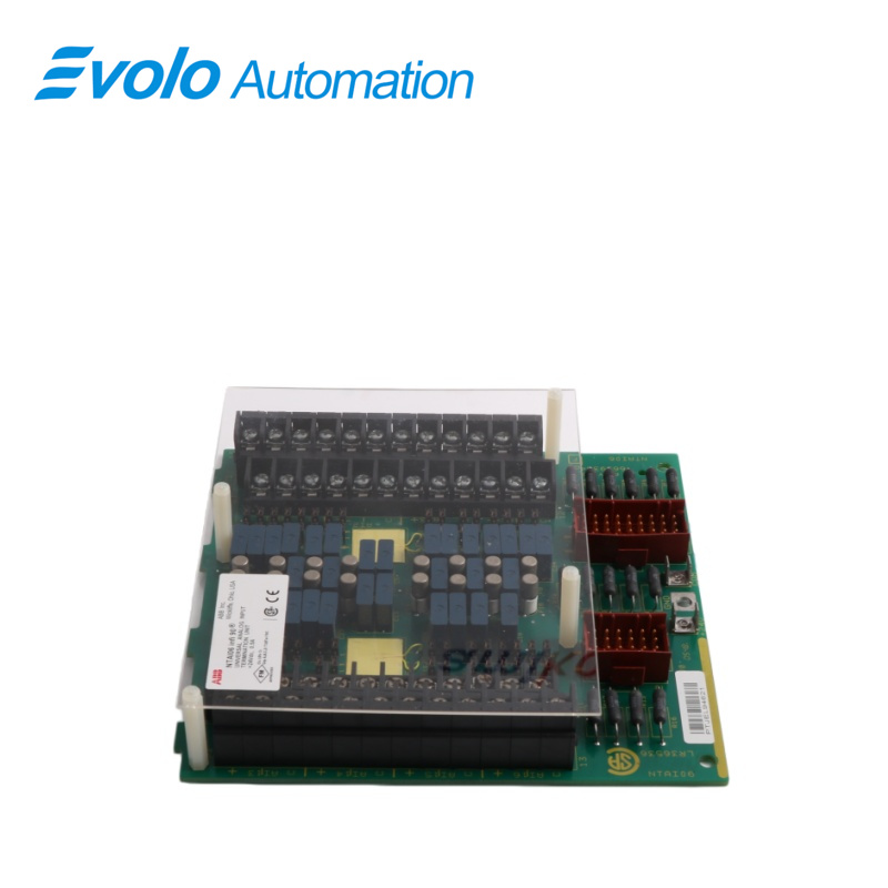
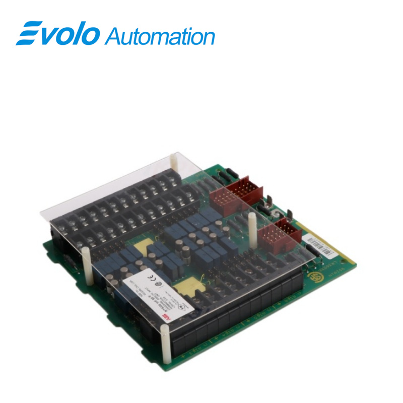
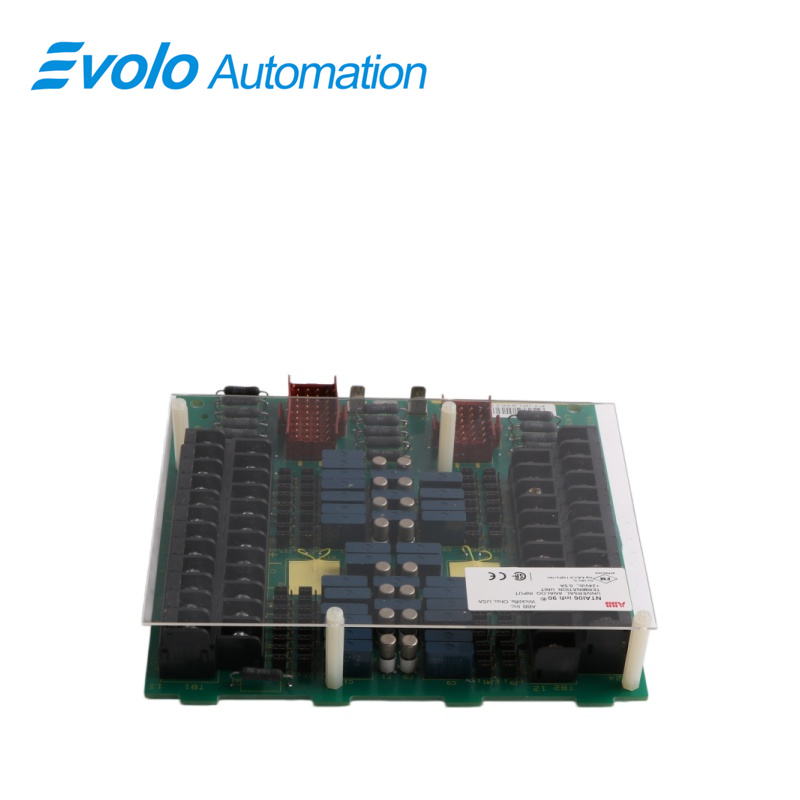
The NTAI06 is a single printed circuit board that mounts in a NFTP01 Field Termination Panel. The termination unit (TU) has two connectors P1 and P2. A single Y-shaped cable connects to P1 and P2 on the termination unit. The other end of the cable connects to the slave module. The terminal blocks for field wiring are on the TU. Jumpers on the NTAI06 are set to match the type of input signal.
The NTAI06 handles up to 16 analog inputs. Each voltage input may be differential or single ended. The IMASI03 can input these analog signal ranges:
• 1 to 5 VDC.
• 0 to 5 VDC.
• 0 to 10 VDC.
• -10 to +10 VDC, or user specified range within ± 10 VDC.
• System powered 4 to 20 mA DC.
• Externally powered 4 to 20 mA DC.
• Three-wire RTD.
• -100 to 100 mV.
• Thermocouple inputs.
Applications
Thermal power plants: Monitoring critical temperature points in boiler furnaces, superheaters, reheaters, and turbine bearings.
Oil/chemical plants: Multi-point temperature monitoring inside reactors, and high-temperature measurement in cracking furnaces and heating furnaces.
Iron and steel metallurgical plants: Temperature data acquisition for blast furnace cooling walls, hot blast stoves, and continuous casting production lines.
Glass/cement plants: Monitoring the ultra-high temperature environment inside melting furnaces and rotary kilns.
FEATURES
1 A standard factory-wired cable connects the TU to the slave module.
2 On-board compression fitting type terminal blocks accept field wiring for 16 inputs.
3 Each TU fits in a standard field termination panel.
4 4 to 20 mA inputs may be either system or externally powered. Input channel transient and surge protection.
5 Analog input signal routing to the IMASI03.
6 Jumper configured input signal types: System powered 4 to 20 mA inputs have individually fused channels. Field powered 4 to 20 mA. Single ended voltage inputs have the minus input terminal jumpered directly to I/O COM on the NTAI06. Differential voltage inputs and three-wire RTDs have the plus and minus and C terminals isolated with respect to I/O COM and module common.
7 Source of the local cold junction reference for thermocouple inputs.
8 Termination point for the shield of the NKAS01 or NKAS11 cable.
9 The termination unit can be located up to 60 meters (200 feet) from the IMASI03.
SPECIAL H ANDLING
1. Use Antistatic Bag. Keep the modules in the antistatic bag until you are ready to install them in the system. Save the bag for future use.
2. Ground Bags Before Opening. Before opening a bag containing an assembly with CMOS devices, touch it to the equipment housing or ground to equalize charges.
3. Avoid Touching Circuitry. Handle assemblies by the edges; avoid touching the circuitry.
4. Avoid Partial Connection of CMOS Device. Verify that all
devices connected to the modules are properly grounded before using them.
5. Ground Test Equipment.
6. Use an Antistatic Field Service Vacuum to remove dust from the module if necessary.
7. Use a Grounded Wrist Strap. Connect the wrist strap to the appropriate grounding plug on the power entry panel. The grounding plug on the power entry panel is connected to the cabinet chassis ground.
REPLACEMENT
1. Turn OFF the INFI 90 cabinet power or unplug the slave module from the MMU backplane.
2. Remove the four nylon screws and remove the RTD cover.
3. Label and remove all field wiring from the terminal blocks.
4. Label and disconnect all cables connected to the TU.
5. Label and disconnect system I/O power and ground from the terminals.
6. Remove the two screws securing the TU to the field termination panel and the chassis common screw and remove the TU.
7. Install the jumpers on the new TU according to installation instructions. Verify the jumpers on the replacement TU.
8. Insert the tabs of the circuit board into the proper slots of the field termination panel standoff and slide the circuit board into position.
9. Secure the termination unit circuit board to the field termination panel with two screws. Do not overtighten.
10. Install the chassis ground screw and number 10 external star washer. Do not overtighten.
11. Reconnect all field wiring removed in Step 2.
12. Reconnect the system I/O power wires and system ground wires removed in Step 3 and verify connections.
13. Reconnect all cables removed in Step 4.
14. Replace the RTD cover and the four nylon screws. Do not overtighten.
15. Energize the cabinet power supply that provides power to the TU.
16. Turn on any external power supplies providing I/O power.
17. Plug in the slave module to the MMU backplane.
FAQ
Q: Can the NTAI06 directly connect to a 4-20mA signal?
A: No. It is designed for mV signals and does not have a built-in 250-ohm sampling resistor. Connecting a current signal will cause numerical overflow or damage to the circuit.
Q: Why is the temperature displayed on the DCS several degrees higher than the actual ambient temperature about NTAI06?
A: Check if the cabinet containing the NTAI06 has good heat dissipation. If the internal temperature of the cabinet is high, the cold junction compensation sensor measures the internal temperature of the cabinet, not the actual ambient temperature.
Q: Do I need to modify the control program (logic) after replacing the NTAI06?
A: No. However, you must ensure that the DIP switch settings on the new board are consistent with the old board to match the correct thermocouple type.
Q: What will the NTAI06 do if the thermocouple disconnects?
A: The system will usually report an "Open Circuit" fault, and the reading on the DCS will jump to the maximum or minimum value (depending on the configuration settings).
Q: Can the cold junction compensation of the NTAI06 be turned off?
A: You can select "External Compensation" or "Internal Compensation" through DIP switches or software configuration. The default is usually onboard internal compensation.