EN
EN




- Overview
- Specifications
- Description
- Applications
- FEATURES
- SPECIAL HANDLING
- REPLACEMENT
- FAQ
- Recommended Products
Overview
Place of Origin: |
Sweden |
Brand Name: |
ABB |
Model Number: |
NTAI05 |
Packaging Details: |
Original new Factory Sealed |
Delivery Time: |
5-7 days |
Payment Terms: |
T/T |
Supply Ability: |
In stock |
Specifications
|
Parameter |
Specification |
|
Model |
NTAI05 |
|
Device Type |
Analog Input Termination Unit |
|
Dimensions |
78.74 × 215.9 × 233.68 mm (D×H×W) |
|
Channels |
16 (High Level) |
|
Application |
Use with FEC, NKTU |
|
Power Requirements |
+24 V DC |
|
Input Current |
20 mA per input |
|
Mounting |
Installs in NFTP01 Field Termination Panel |
|
Operating Temperature |
0 °C to +70 °C |
|
Humidity |
0–95 % up to 55 °C; 0–45 % up to 70 °C (non-condensing) |
|
Atmospheric Pressure |
Sea level to 3 km |
|
Air Quality |
Non-corrosive environment |
|
EMI/RFI Precautions |
Keep cabinet doors closed; maintain ≥2 m from communication equipment |
|
Cooling Requirements |
No cooling required within specified limits |
|
Certification |
CSA certified for process control equipment in non-hazardous locations |
|
WEEE Category |
Small Equipment (no external dimension >50 cm) |
|
Number of Batteries |
0 |
Description
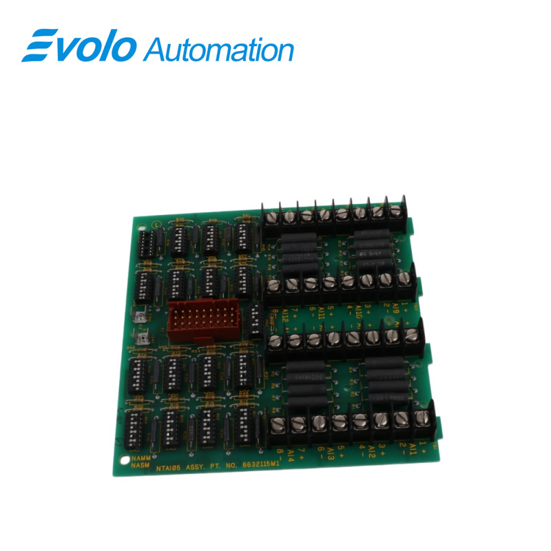
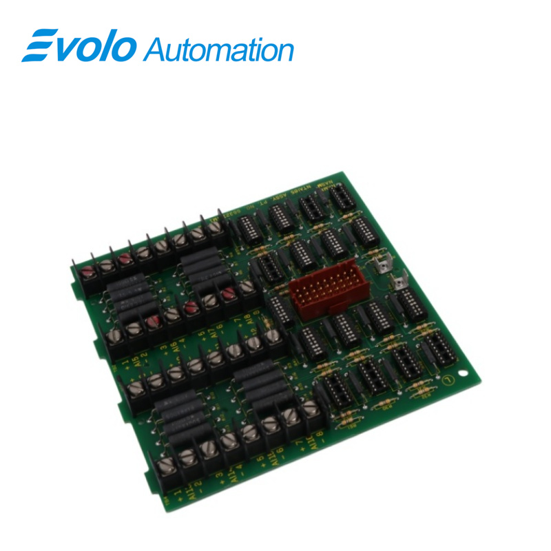
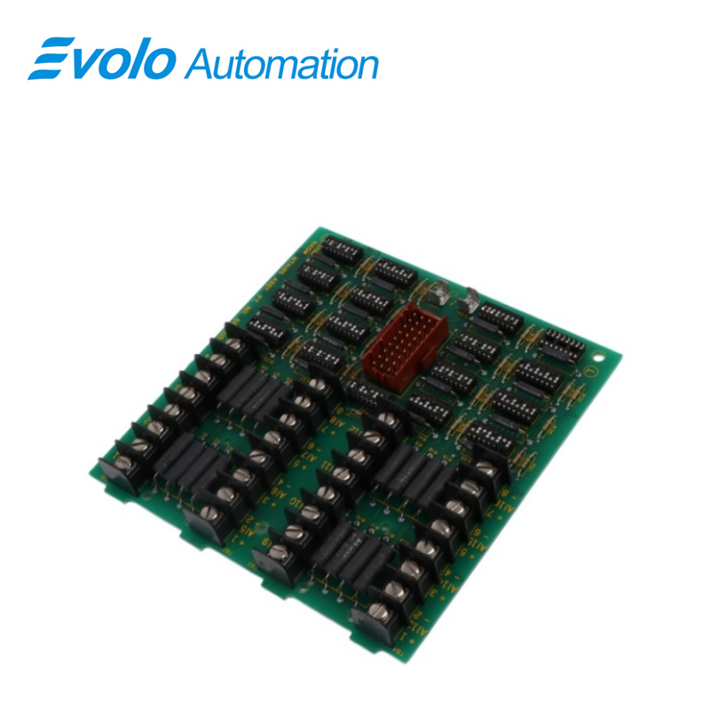
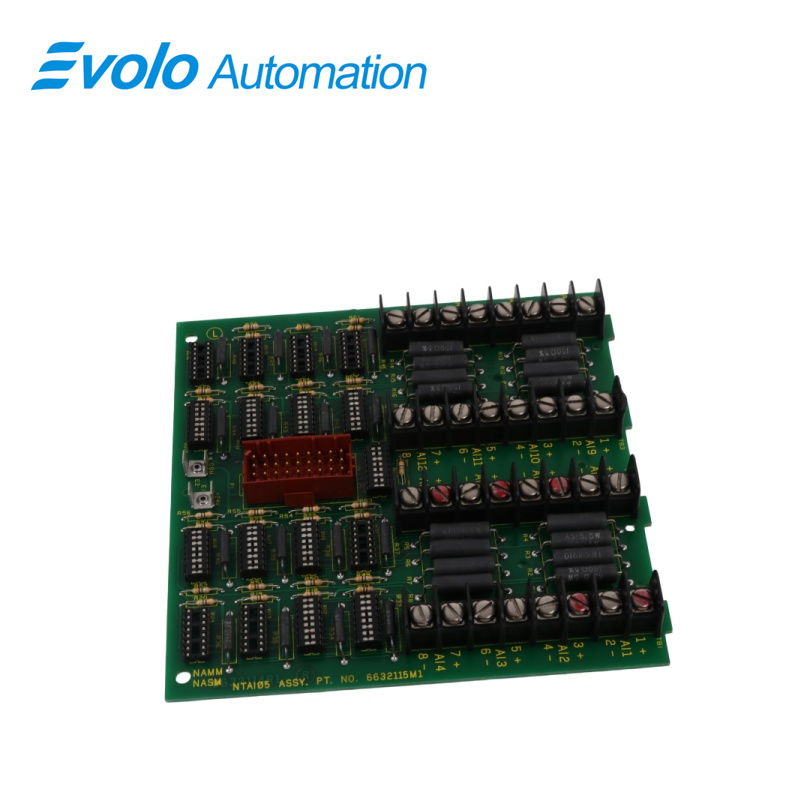
The NTAI05 Analog Input Termination Unit inputs 15 or 16 channels of analog signals depending on slave module type. It connects a slave module to field equipment and Bailey Controls smart transmitters. The signals pass through slave modules to the IMMFP01, IMMFP02 and IMMFP03 INFI 90 Multi-Function Processors, IMAMM03 Analog Master Modules or NMFC03, NMFC04 and NMFC05 Multi-Function Controllers. The NTAI05 unit is a single printed circuit board that mounts to an NFTP01 Field Termination Panel. The termination unit (TU) has one cable connector for signals. P1 carries the inputs to the slave module through the cable. The terminal blocks for field wiring are on the termination unit. The dipshunts on the NTAI05 unit set the input type. Refer to the appendix for the switch settings of the slave module used. Be sure to check the switch setting before inserting the module into the module mounting unit (MMU).
Applications
Power plants: Monitor boiler feedwater flow, turbine lubricating oil pressure, and generator set temperature.
Oil/chemical plants: Monitor reactor pressure, storage tank levels, and pipeline flow transmitter signals.
Paper/pulp mills: Used for flow and concentration sensor connections in pulp processing systems.
Large water treatment plants: Monitor inlet and outlet water pump station pressure, pH value, and flow data.
FEATURES
A standard factory-wired cable connects the termination unit to the slave module.
On-board terminal blocks accept field and I/O wiring.
Analog inputs routed between field devices and I/O modules.
The termination unit has no serviceable parts.
Inputs may be either system or externally powered
The NTAI05 unit handles up to 15 analog inputs for the IMASI02 and IMFBS01 modules or 16 analog inputs for the IMASM01 modules (inputs may be differential or single ended). The input signal types that can be handled by the various slave modules and configured by dipshunts on the NIAI05 unit are listed.
• 4 to 20 milliamps DC, system or externally powered.
• -10 VDC to +10 VDC.
• 0 VDC to 10 VDC.
• 1 VDC to 5 VDC.
• 0 VDC to 5 VDC.
• 0 VDC to 1 VDC (IMASI02/IMFBS01 only).
SPECIAL HANDLING
1. Use Static Shielding Bags. Keep the modules in the static shielding bag until they are ready to be used in the system. Save the bag for future use.
2. Ground Bags Before Opening. Before opening a bag containing an assembly with CMOS devices, touch it to the equipment housing or ground to equalize charges.
3. Avoid Touching Circuitry. Handle assemblies by the edges; avoid touching the circuitry.
4. Avoid Partial Connection of CMOS Device. Verify that all devices connected to the modules are properly grounded before using them.
5. Ground Test Equipment.
6. Use an Antistatic Field Service Vacuum. Remove dust from the module if necessary.
7. Use a Grounded Wrist Strap. Connect the wrist strap to the appropriate grounding plug on the power entry panel. The grounding plug on the power entry panel is connected to the DC common bus.
8. Do Not Use Lead Pencils to Set Dipswitches. To avoid contamination of switch contacts that can result in circuit board malfunction, do not use a lead pencil to set a dipswitch.
REPLACEMENT
1. Turn off the INFI 90 cabinet power.
2. Pull the associated slave module out of the cable connector.
3. Label and remove all field wiring from the terminal blocks.
4. Label and disconnect the cable connected to the termination unit.
5. Label and disconnect system I/O power and ground wires from the terminals.
6. Remove the two number 10 screws securing the termination unit to the field termination panel.
7. Remove the dipshunts from the defective termination unit and place them in the same socket of the new termination unit (or cut the dipshunts included with the replacement unit). Be sure to install the dipshunt correctly so that no pins are bent over.
8. Insert the tabs of the replacement circuit board into the proper slots of the field termination panel stand-off and slide the circuit board into position.
9. Secure the termination unit circuit board to the field termination panel with the two number 10 screws.
10. Connect all field wiring removed in Step 3 and verify connections.
11. Connect the system I/O power and ground wires removed in Step 5 and verify connections.
12. Connect the cable removed in Step 4 and verify the connection.
13. Energize the cabinet power supply that provides power to the termination unit.
14. Turn on any external power supplies providing I/O power.
15. Insert the slave module into the MMU backplane.
FAQ
Q: Does the NTAI05 support 2-wire transmitter power supply?
A: The NTAI05 is primarily responsible for signal conversion. 2-wire instruments typically require a matching power distribution board (such as NAPA) or external power supply for their 24V power.
Q: If one channel fails, will NTAI05 affect the other 15 channels?
A: Usually not. The NTAI05 channels are designed relatively independently; a physical wiring fault in a single channel will not interfere with other circuits.
Q: What is the difference between the NTAI05 and NTAI06?
A: The NTAI05 is used for general high-level signals (1-5V/4-20mA), while the NTAI06 is typically designed for low-level microvolt signals such as thermocouples (TC) and features cold junction compensation.
Q: Why does the DCS display "Input Open Circuit," but the field instruments have outputs about NTAI05?
A: Please check if the multi-core communication cable (NKTU) between the NTAI05 and the I/O module is properly connected, or if the sampling resistor for that channel is burnt out.
Q: Does replacing the NTAI05 terminal board require reprogramming?
A: No. It is a purely hardware interface board. After replacement, simply confirm that the wiring is correct and the card recognizes the signal.