EN
EN




- Overview
- Specifications
- Description
- Applications
- INSTALLATION
- OPERATIONS
- FREQUENTLY ASKED QUESTIONS
- Recommended Products
Overview
Place of Origin: |
USA |
Brand Name: |
GE |
Model Number: |
IS200VCRCH1B |
Packaging Details: |
Original new Factory Sealed |
Delivery Time: |
5-7 days |
Payment Terms: |
T/T |
Supply Ability: |
In stock |
Specifications
|
Part Number: |
IS200VCRCH1B |
|
Manufacturer: |
General Electric |
|
Country of Origin: |
USA |
|
Product Type: |
I/O Board (Contact Input/Relay Output) |
|
Series: |
Mark VI |
|
Number of Channels: |
48 Dry Contact Voltage Input Channels |
|
Input Voltage: |
125 V DC (100-145 V DC) |
|
Input Isolation: |
1500 V |
|
Filter: |
4 ms for noise and contact bounce, AC voltage rejection 60 V RMS (50/60 Hz) |
|
Operating Temperature: |
-10 °C to 60 °C |
|
TMR Plugs: |
JR1, JS1, JT1 |
|
Dimensions: |
2 x 18.6 x 26.1 cm |
|
Weight: |
0.32 kg |
Description
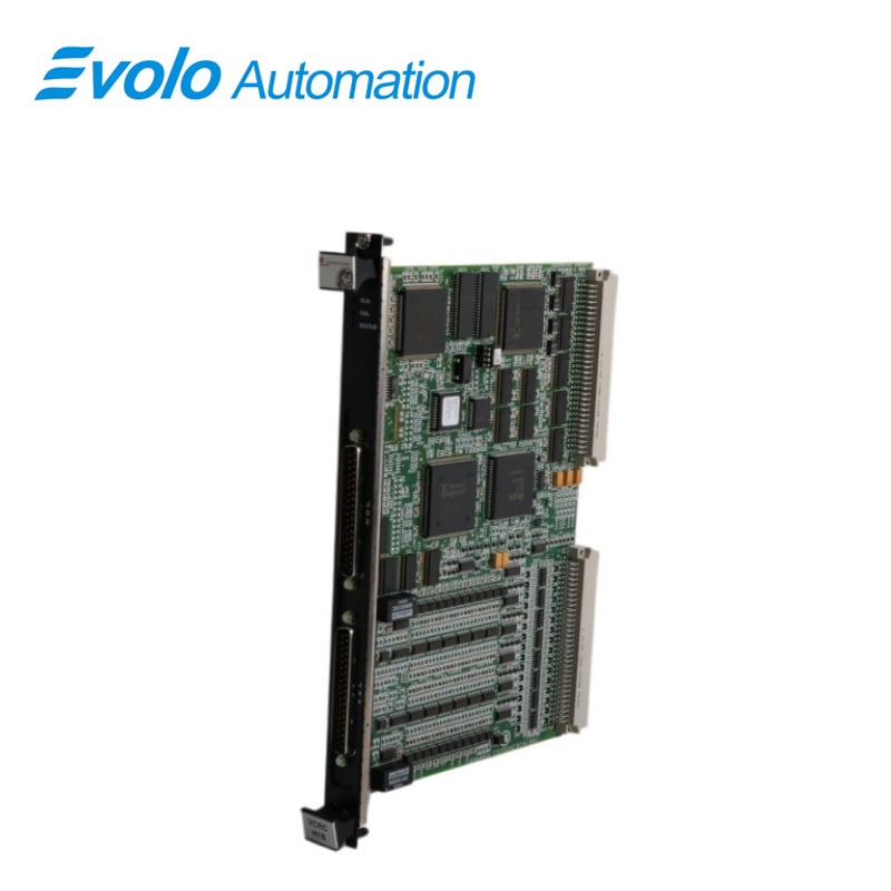
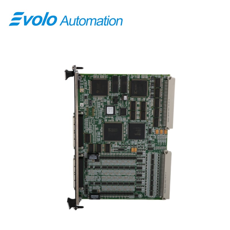
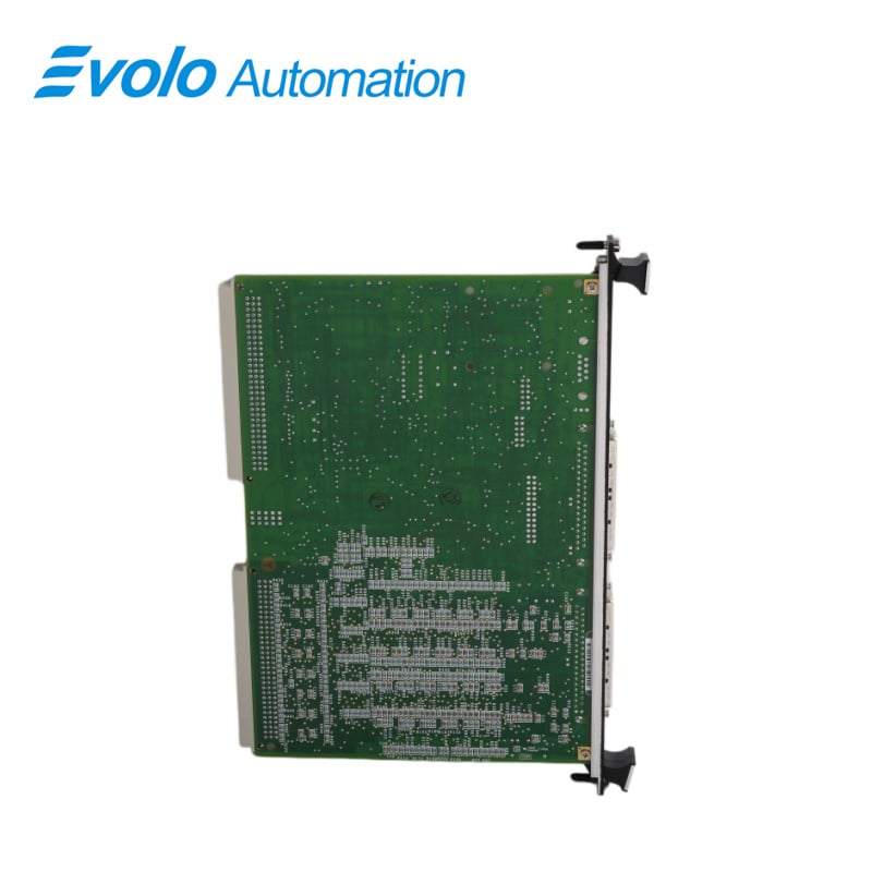
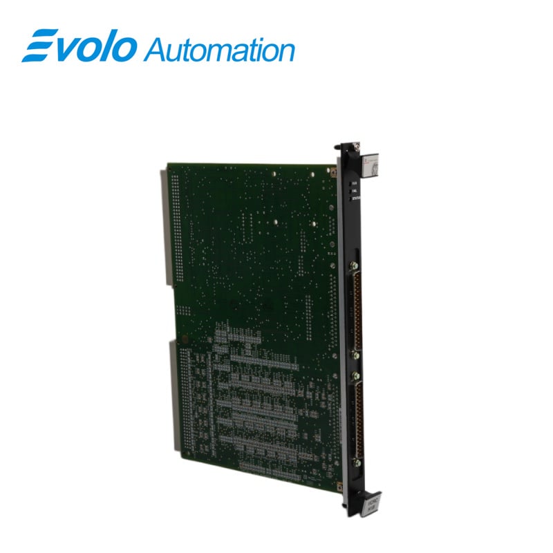
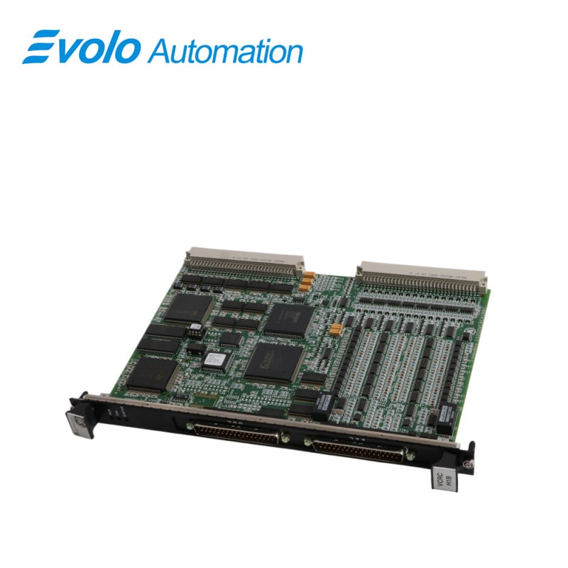
IS200VCRCH1B is a Contact Input/Relay Output Board manufactured by General Electric as part of the Mark VI series used in gas turbine control systems. The Contact Input/Relay Output Board accepts 48 discrete inputs and manages 24 relay outputs from a total of four-terminal boards through its accompanying daughterboard. The double-width VCCC module fits in the VME I/O rack. Two sets of J3/J4 connections are provided in this rack for cabling to the TBCl and TRLY terminal boards. In place of the VCCC, the VCRC is a narrower board that can be used.
Applications
Power Generation Industry: Widely used in GE Frame 6, 7, and 9 series gas turbines and large steam turbine power plants.
Core Functions: Controls key auxiliary equipment in power plants, such as fuel shut-off valves, lubricating oil pump starters, cooling fan interlocks, and unit alarm systems.
Oil and Chemical Plants: Used for logic control of large compressor drive units, ensuring safe shutdown of the production line via relay logic in case of process anomalies.
INSTALLATION
1. Turn off the processor rack for the VME I/0.
2.To seat the edge connectors, slide in the VCCC board and push the top and bottom levers in with your hands.
3. Tighten the captive screws on the front panel's top and bottom
4. Switch on the VME rack and look at the front-panel diagnostic lights.
OPERATIONS
1 The input voltages in the VCCC are sampled at the frame rate for control functions and at 1 ms for SOE reporting after passing through optical isolators. The signals are delivered to the VCMI via the VME backplane. The controller receives them next from the VCMI. The processing of contact input is depicted in the following figure. The dry-contact inputs are powered by a floating 125 V DC (100-145 V DC) supply.
2 Filters on each input control surge and decrease high-frequency noise close to the signal exit. A 4 ms filter is used to filter out noise and contact bounce. With 125 V DC excitation, the AC voltage rejection (50/60 Hz) is 60 V RMS.
3 For TMR applications, plugs JR1, JS1, and JT1 provide contact input voltages to the three VME board racks R, S, and T. Each controller rack's VCMI board votes on the outcomes once the three VCCCs have analyzed the signals. Relay control signals and monitor feedback voltages are transmitted between VCCC and TRLY through cables.
4 The relay board is mounted with relay drivers, fuses, and jumpers. TRLY, DRLY, and SRLY are just a few of the different relay board kinds that can be driven. The failsafe features on the relay outputs allow the inputs to vote to de-energize the corresponding relays when a cable is unplugged. The relays de-energize likewise if communication with the connected VME board is lost.
FREQUENTLY ASKED QUESTIONS
Q: Why are monitoring and speed control required in a turbine of IS200VCRCH1B?
A: Heat is generated in an atomic power station by nuclear fusion, water is heated and steam is generated to power the turbine. To maintain the frequency F, it is necessary to keep a constant speed of 1500 RPM. The home setup is affected by changes in frequency.
Q: What does a printed circuit board (PCB) do of IS200VCRCH1B?
A: A printed circuit board, or PCB, is a device that uses conductive paths, tracks, or signal lines etched from copper sheets laminated onto a non-conductive substrate to mechanically support and electrically connect electronic components.
Q: What is an output module in PLC of IS200VCRCH1B?
A: Output Module for PLC. PLC analog outputs, which are extensively used in industrial applications to operate actuators, valves, and motors, use typical analog output ranges such as 5V, 10V, 0V to 5V, 0V to 10V, 4 to 20 mA, or 0 to 20 mA.