EN
EN




- Overview
- Specifications
- Description
- IS200TGENH1A is a Terminal Board Generator Monitor developed
- Operation
- Installation
- Diagnostics
- Frequently Asked Questions
- Recommended Products
Overview
Place of Origin: |
USA |
Brand Name: |
GE |
Model Number: |
IS200TGENH1A |
Packaging Details: |
Original new Factory Sealed |
Delivery Time: |
5-7 days |
Payment Terms: |
T/T |
Supply Ability: |
In stock |
Specifications
|
Part Number: |
IS200TGENH1A |
|
Manufacturer: |
General Electric |
|
Country of Manufacture: |
United States of America (USA) |
|
Product Type: |
Terminal Board Generator Monitor |
|
Weight: |
4.00 lbs |
|
Dimensions: |
15.00 x 9.00 x 3.00 |
|
Series: |
Mark VI |
|
Voltage Input Range: |
±5 Vdc to ±10 Vdc |
|
Normal Current Range: |
0 to 5 A |
|
Over-Range Current: |
up to 10 A |
|
Nominal Frequency: |
50/60 Hz |
|
Frequency Range of Interest: |
45 to 66 Hz |
|
Magnetic Isolation: |
up to 1,500 V RMS |
|
Input Load per Circuit: |
Less than 0.5 |
|
Inputs to VGEN and TGEN: |
Two 3-phase generators and bus PTs, Three 1-phase generator CTs, Four analog inputs |
Description
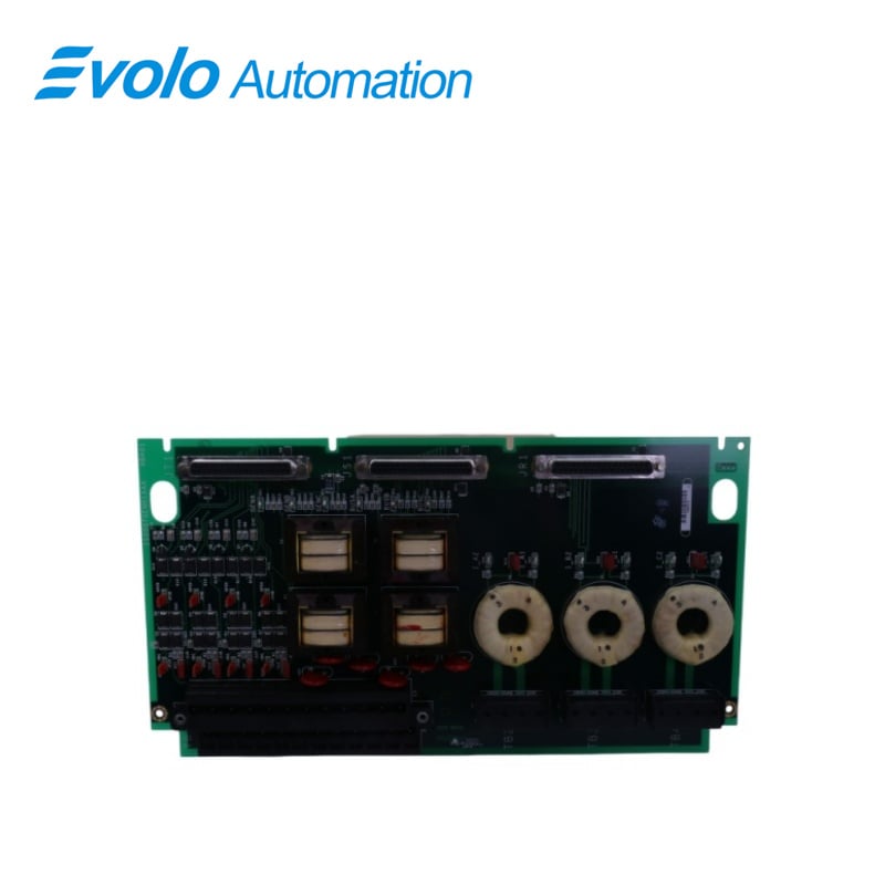
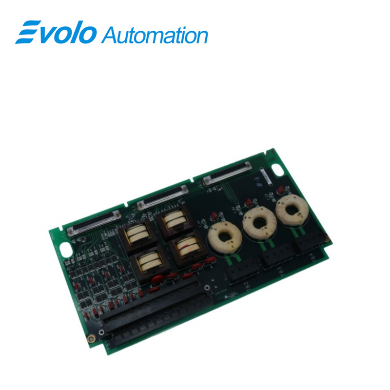
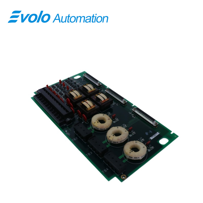
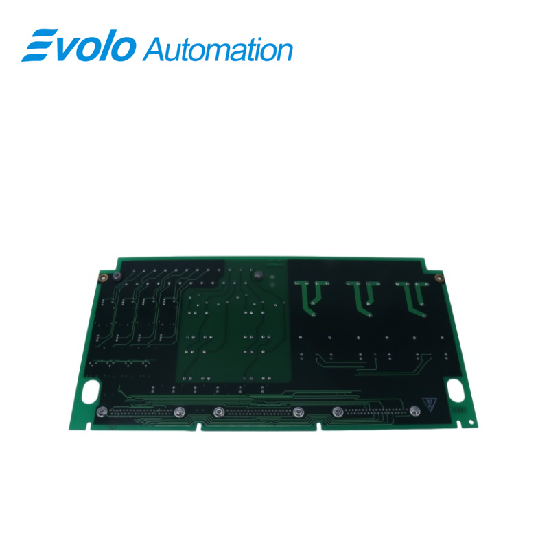
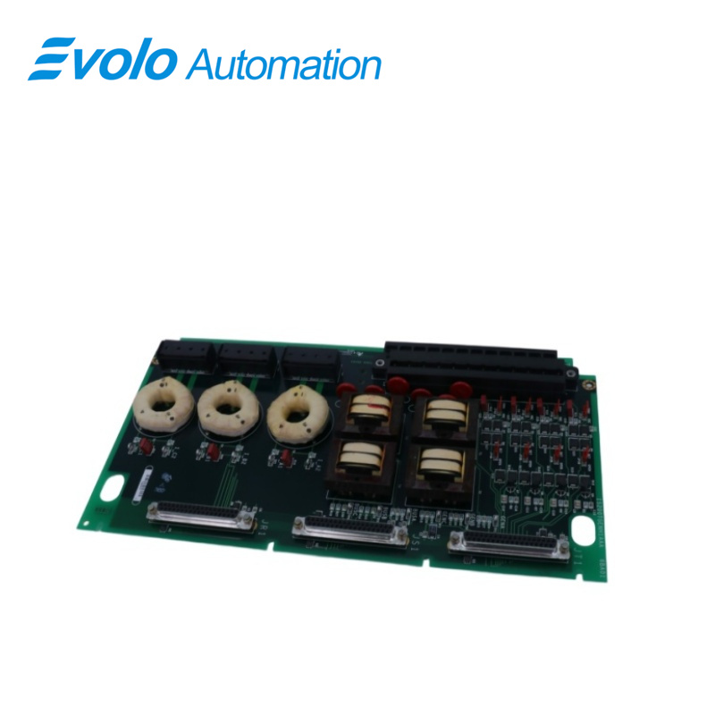
IS200TGENH1A is a Terminal Board Generator Monitor developed by GE under the Mark VI series. The Generator Monitor (TGEN) terminal board communicates with the VGEN processor to monitor the three-phase voltage and currents of the generator, as well as to calculate the three-phase power and power factor. VGEN provides the PLU and EVA capabilities for large steam turbine applications by utilizing fast-acting solenoids situated on the TRLY terminal board. The TGEN in the Mark VI system collaborates with the VGEN processor and supports simplex and TMR applications. A single cable links one TGEN to the VGEN.TGEN connects to three VGEN boards through three distinct wires in TMR systems.
IS200TGENH1A is a Terminal Board Generator Monitor developed
Thermal Power Plants: Widely used in GE Frame 6, 7, and 9 series gas turbines, it is an essential component of the Mark VI control cabinet.
Cogeneration Plants (CHP): Used in self-contained power plants in chemical plants or paper mills where precise turbine speed regulation is required to match grid load.
Hydropower Plants: Used for frequency synchronization and overspeed protection monitoring of hydroelectric generators.
Operation
1 TGEN's two- and three-phase PT inputs, as well as three- and one-phase current transformer (CT) inputs, are monitored by VGEN. Four analog inputs can be adjusted for 4-20 mA or 5, 10, 20 V DC using jumpers. The phase of the input signals is checked using test points on the generator and bus voltages and currents. VGEN converts signals and calculates power, power factor, and frequency.
2 To verify the phase in the field, test points are provided for all PT and CT inputs. Three single-phase CT inputs with a continuous normal current range of 0 to 5 A are provided. TGEN's CTs are magnetically isolated. CT terminations are non-pluggable terminal blocks with captive lugs that accept wires up to #10 AWG.
3 The four analog inputs can accept 4-20 mA or 5-10 V DC signals. A +24 V DC source is available for all four circuits, each with its own current limit. The 4-20 mA transducer can be connected to either the turbine control's +24 V DC source or as a self-powered source.
Installation
The installation process involves wiring the analog current and potential transformer (PT) inputs to specific terminal blocks on the system. Here's a detailed expansion of
this installation procedure:
1 Wiring Analog Current and Potential Transformer Inputs: The analog current and potential transformer inputs are connected to terminal block 1. These transformers are crucial components for measuring current and voltage within the system, facilitating accurate readings for monitoring and control purposes.
2 Current Transformer Wiring to Special Terminal Blocks: The current transformers (CT) have dedicated wiring points located at special terminal blocks TB2, TB3, and TB4. These specific terminal blocks are designed to prevent the unplugging of CT connections, ensuring a safeguard against an open circuit scenario. This protective measure aims to maintain system integrity and accuracy by securing the CT connections.
3 Jumper Settings for Desired Input Configuration: Jumpers labeled as J1A and J1B are used to set the desired input configuration, specifically for analog inputs 1 through 4. These jumpers allow users to configure whether the inputs should operate based on current or voltage signals. Adjusting these jumpers helps align the system's input type (current or voltage) with the nature of the connected sensors or devices.
4 Purpose of Jumper Settings: J1A and J1B jumpers play a pivotal role in configuring the system's input preferences. By setting these jumpers, users can specify whether the analog inputs 1 through 4 should be configured for receiving current or voltage signals. This configuration flexibility enables the system to adapt to varying sensor or device requirements for accurate signal interpretation.
5 Ensuring Desired Input Type: Proper configuration of jumpers J1A and J1B is essential to ensure that the analog inputs 1 through 4 are set to the desired input type (current or voltage). This alignment ensures compatibility and accurate signal processing within the system.
Diagnostics
1 Diagnostics check the input signal for a high/low (hardware) limit and a high/low system (software) limit.
2 The software limit check can be changed in the field. Voltage inputs have open wire detection, and relay drivers and coil currents are monitored. The terminal board's connectors JR1, JS1, and JT1 each have their own ID device that is interrogated by the l/O board.
3 The ID device is a read-only chip that contains the serial number, board type, revision number, and plug location of the terminal board.
Frequently Asked Questions
Q: What is IS200TGENH1A?
A: IS200TGENH1A is a Terminal Board Generator Monitor developed by GE under the Mark VI series.
Q: What is the function of the IS200TGENH1A?
A: The TGEN board, together with the generator board VGEN, monitors the generator's three-phase voltage and currents and calculates three-phase power and power factor.
Q: What is the voltage input range of IS200TGENH1A?
A: The voltage input ranges from ±5 Vdc to ±10 Vdc.
Q: Does the IS200TGENH1A support Simplex and TMR systems?
A: Yes, TGEN supports both Simplex and TMR systems.