EN
EN




- Overview
- Specifications
- Description
- Applications
- SPECIAL HANDLING
- FAQ
- Recommended Products
Overview
Place of Origin: |
Sweden |
Brand Name: |
ABB |
Model Number: |
IMDSO14 |
Packaging Details: |
Original new Factory Sealed |
Delivery Time: |
5-7 days |
Payment Terms: |
T/T |
Supply Ability: |
In stock |
Specifications
|
Parameter |
Value |
|
Model |
IMDSO14 |
|
Description |
Digital Output Module |
|
Dimension |
3.7x31.7x17.8 cm |
|
Weight |
0.2 kg |
|
Power Supply Voltage |
5 VDC (±5%) |
|
Current Consumption |
275 mA typical; 370 mA maximum |
|
Logic Power Dissipation |
1.375 W typical; 1.850 W maximum |
|
Overvoltage Category on Outputs |
II per IEC 1010-1 |
|
Outputs |
16 digital |
|
Load Voltage |
24 VDC, 48 VDC |
|
Load Current (Max) |
250 mA at 24 VDC; 125 mA at 48 VDC |
|
Off Leakage Current (Max) |
10 µA at 70°C (158°F) |
|
On Voltage Drop (Max) |
2 V at 70°C (158°F) |
|
Output Current Consumption |
24 VDC: 150 mA typical, 250 mA max per output; 48 VDC: 75 mA typical, 125 mA max per output |
|
Electrostatic Discharge (IEC 1000-4-2, EN 61000-4-2) |
Contact: ±6 kV; Air: ±8 kV |
|
Power Frequency Magnetic Field (IEC 1000-4-8, EN 61000-4-8) |
Continuous: 30 A/m (rms); Short duration: 300 A/m (rms) |
|
Pulse Magnetic Field (IEC 1000-4-9, EN 61000-4-9) |
Peak: 300 A/m |
|
Damped Oscillatory Magnetic Field (0.1–1 MHz) (IEC 1000-4-10, EN 61000-4-10) |
Peak: 30 A/m |
|
Radiated RF Electromagnetic Field (80 MHz–1 GHz, ENV 50140) |
Unmodulated rms: 10 V/m; AM 80% (1 kHz) |
|
Radiated RF Field (900 ±5 MHz, ENV 50204) |
Unmodulated rms: 10 V/m; Pulse modulated, 50% duty cycle, 200 Hz |
|
Radio-Frequency Common Mode (0.15–80 MHz, ENV 50141) |
Unmodulated rms: 10 V/m; AM 80% (1 kHz); Source impedance: 150 Ω |
|
Operating Temperature |
0° to 70°C (32° to 158°F) (internal cabinet rating) |
|
Relative Humidity |
5% to 95% up to 55°C; 5% to 45% at 70°C (non-condensing) |
|
Pollution Degree |
1 (no condensation) |
|
Atmospheric Pressure |
Sea level to 3 km (1.86 miles) |
Description
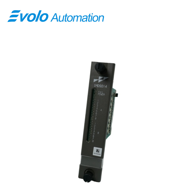
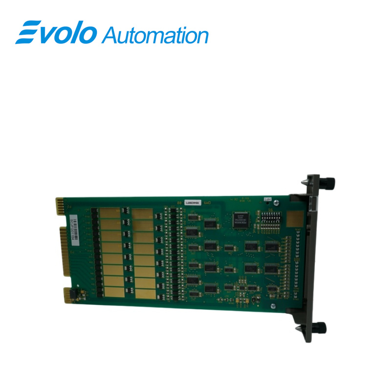
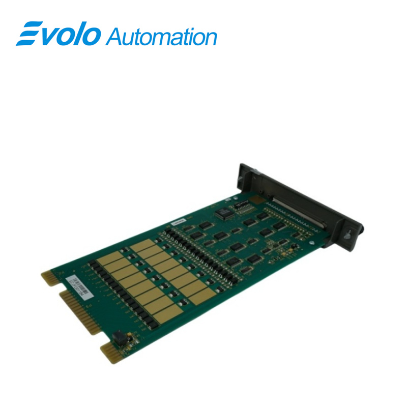
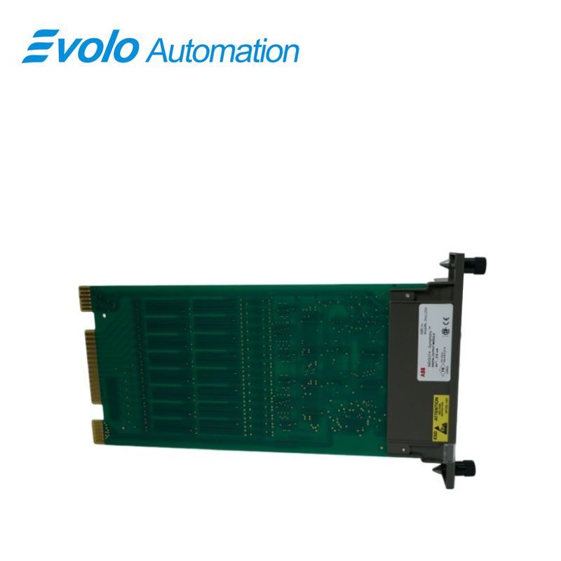
The IMDSO14 DSO module consists of a single printed circuit board that occupies one slot in a module mounting unit (MMU). It outputs 16 separate digital signals through solid state circuits on the printed circuit board. Twelve outputs are isolated from each other; the remaining two pairs share common positive output lines.
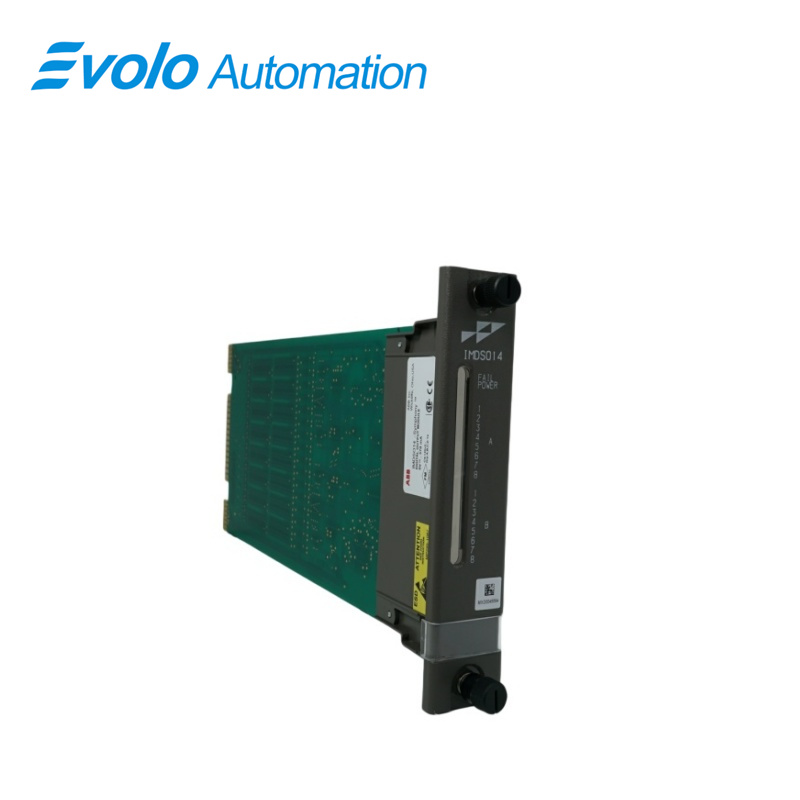
Two captive screws on the faceplate secure the module to the MMU. The upper two front panel red and green LEDs indicate the module operating status. The 16 lower front panel red LEDs (group A and group B) display the module output states (ON or OFF).
The DSO module has three card edge connectors for external signals and power. P1 connects to logic power (+5 VDC) that drives the module circuits. P2 connects the module to the I/O expander bus to communicate with a control module. P3 outputs the digital signals using a cable connected to a termination unit (TU) or a termination module (TM). The terminal blocks (physical connection points) for field wiring are on the TU or TM.
Applications
Power and Energy Plants:
Power Plant Auxiliary Control: Used to control the start-stop logic of feedwater pumps and blowers.
Circuit Breakers and Disconnect Switches: Execute switch-changing commands in the power distribution system.
Oil and Chemical Plants:
Solenoid Valve Control: Drives the solenoid heads of on-site shut-off and regulating valves to control fluid flow.
Safety Interlock Systems: Output signals to trigger emergency shutdown or pressure relief protection when an anomaly is detected.
Heavy Industrial Manufacturing (Paper, Steel, Cement):
Motor Control: Acts as an interface to the Motor Control Center (MCC) to control the operation of conveyor belts and rotating equipment.
Lighting and Alarm Systems: Drives audible and visual alarms, status indicators, and emergency lighting within the plant.
Municipal Utilities (Water Treatment, Waste Incineration): Used for automated program control of dosing pumps and filter valves.
SPECIAL HANDLING
Use the static grounding wrist strap when installing and
removing modules. Static discharge may damage static sensitive devices on modules in a cabinet. Use grounded equipment
and static safe practices when working with static sensitive
devices.
1. Use Static Shielding Bag. Keep the module in its static shielding bag until you are ready to install it in the system. Save the bag for future use.
2. Ground Bags before Opening. Before opening a bag containing an assembly with static sensitive devices, touch it to the equipment housing or ground to equalize charges.
3. Avoid Touching Circuitry. Handle assemblies by the edges; avoid touching the circuitry.
4. Avoid Partial Connection of Static Sensitive Devices. Verify that all devices connected to the modules are properly grounded before using them.
5. Ground Test Equipment.
6. Use an Antistatic Field Service Vacuum. Remove dust from the cards if necessary.
7. Use a Grounded Wrist Strap. Connect the wrist strap to the appropriate grounding plug.
FAQ
Q: What is the IMDSO14?
A: It is a Digital Output Module.
Q: What about your delivery time of IMDSO14?
A: Generally 1-3 days after receiving your payment. The specific delivery time depends on the type and quantity of the order.
Q: How long is the warranty period of IMDSO14?
A: We offer a standard one-year warranty for all new and original products.
Q: Do you offer any discounts?
A: Yes! For discounts on IMDSO14, please contact John for the best offer.