EN
EN




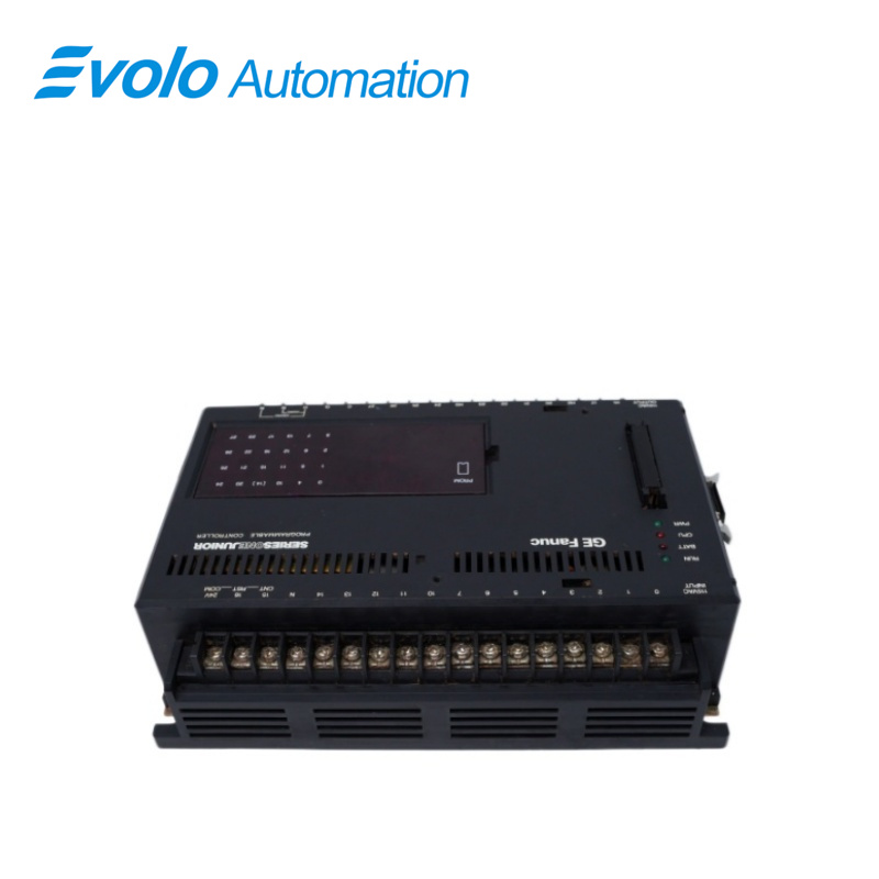
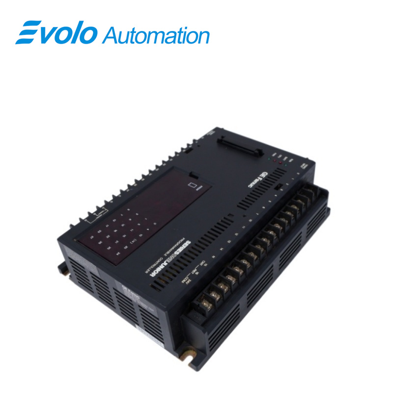
- Overview
- Specifications
- Description
- Applications
- REPLACING A FUSE
- FAQ
- Recommended Products
Overview
Place of Origin: |
USA |
Brand Name: |
GE |
Model Number: |
IC609SJR100 |
Packaging Details: |
Original new Factory Sealed |
Delivery Time: |
5-7 days |
Payment Terms: |
T/T |
Supply Ability: |
In stock |
Specifications
|
Product Name: |
Controller |
|
Model Number: |
IC609SJR100 |
|
Dimensions: |
21.5 x 16.2 x 6.2 cm |
|
Weight: |
1.82 kg |
|
Series: |
Series One Junior |
|
Current Rating: |
2 A (all circuits) |
|
Circuit Connection: |
Soldered |
|
Input Voltage: |
15 VAC |
|
Output Voltage: |
115/230 VAC |
|
Fuse Type: |
Pico, Fast Blow |
Description
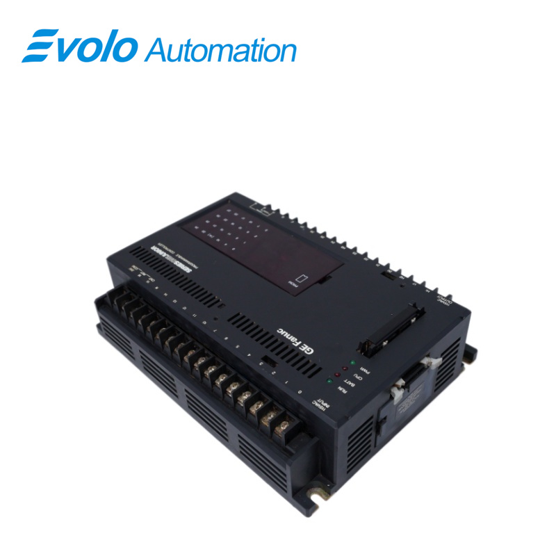
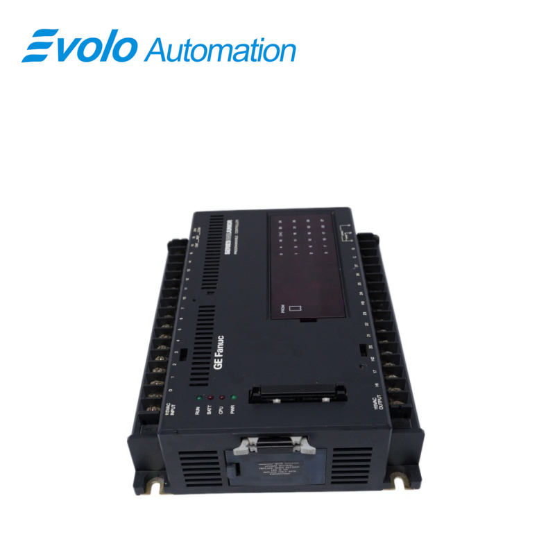
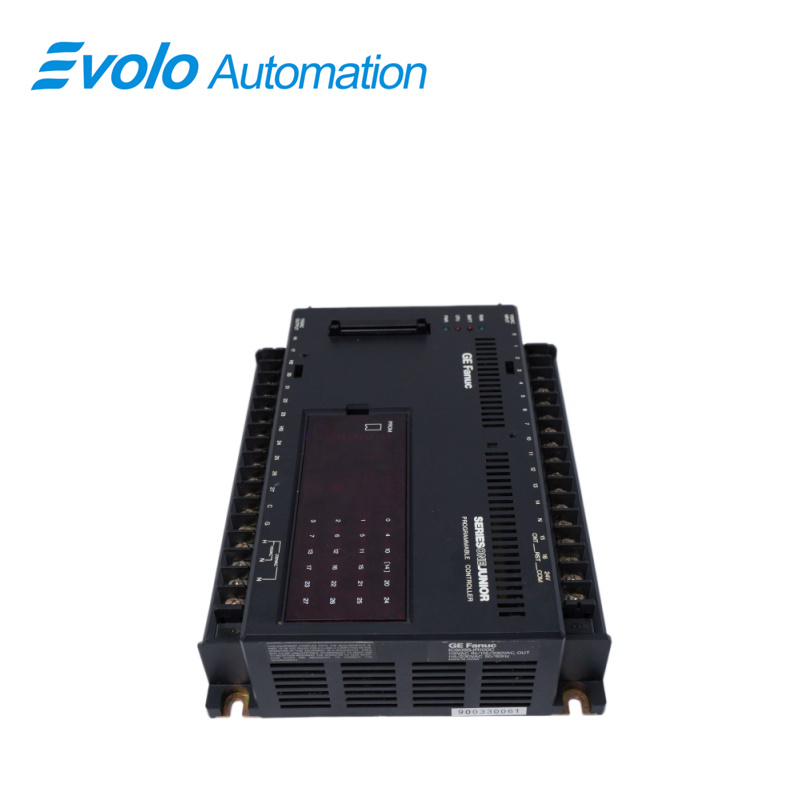
The IC609SJR100 Controller has 9 fuses, with each circuit being individually fused. Each of these is a fast blow pico fuse and is soldered in place. Each fuse is rated at 2 amps. These fuses are physically located in each output line, between the output circuitry and the output terminal (17 through 27).
Applications
Small processing plants: Logic control for stand-alone automated equipment, such as small punch presses and drilling machines.
Food packaging plants: Managing the start/stop of simple conveyor belts, and the sequential control of case packers and sealing machines.
Textile machinery plants: Controlling the simple cyclical operations of single looms or dyeing and finishing equipment.
Plastic products plants: Used for material handling robots or drying equipment around small injection molding machines.
Hardware parts plants: Responsible for logic interlocks on simple automated assembly or testing stations.
Printing and packaging plants: Controlling the sequential operation of auxiliary equipment such as folding machines and paper cutters.
REPLACING A FUSE
If an internal fuse should blow in one of the circuits in a Series One Junior, use the following procedure to access and replace the fuse.
1. Turn OFF the AC or DC power source, as applicable, and remove the programmer (if installed).
2. Remove the plastic covers from over the top and bottom terminal strips.
3. Disconnect power source wiring from terminals on the bottom right.
4. Disconnect field wiring from input terminals at top of unit and output terminals at the bottom of the unit.
5. Remove bottom two bolts holding the basic unit in place. Loosen but do not remove the top bolts.
6. Slide the basic unit up and then pull forward to clear the top mounting bolts.
7. Place the unit on a work bench so that the bottom metal cover plate is accessible.
8. Remove the 4 largest phillips-head screws. One of these screws is located in each of the 4 corners of the cover plate. These screws fasten the cover plate to the black plastic cover.
9. The circuit boards, terminal strips and other hardware items are physically attached to the metal bottom cover plate. The black plastic cover plate must now be detached from the rest of the unit.
FAQ
Q: What is the function of the IC609SJR100?
A: The IC609SJR100 is a Controller within the One Jr. Series.
Q: Where do you connect the 115 V ac IN on the IC609SJR100?
A: The 115 V ac IN connects on the second and third notch.
Q: What shipping methods are used for IC609SJR100?
A: Major carriers like FedEx, DHL, and UPS are primarily used for worldwide delivery.
Q: Do you provide warranty as standard?
A: We provide a full 12-month warranty for IC609SJR100. If any problems occur within 12 months from the delivery date, you can contact our team for guidance and support.
Q: How to Check Price and Availability for IC609SJR100?
A: Please contact John Yang for sales at +86-18150117685 or request a quote.