EN
EN




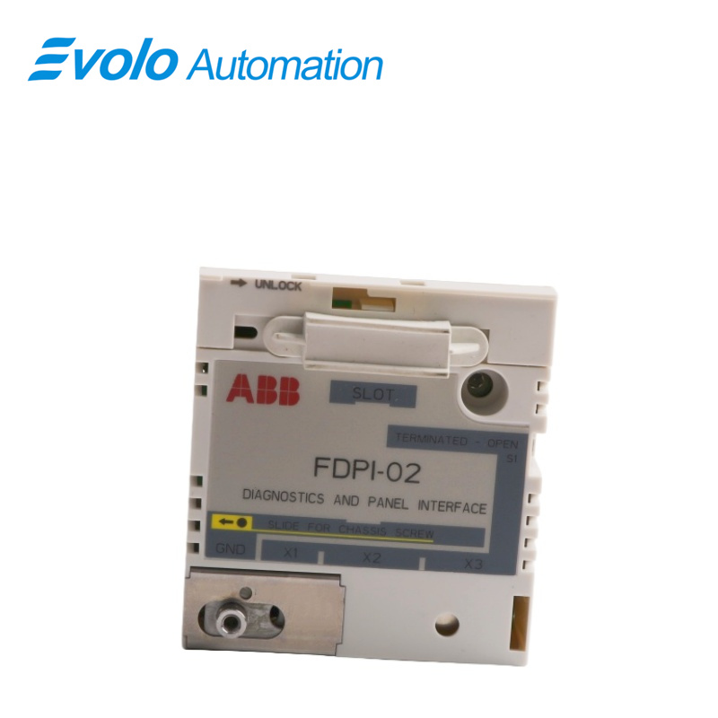
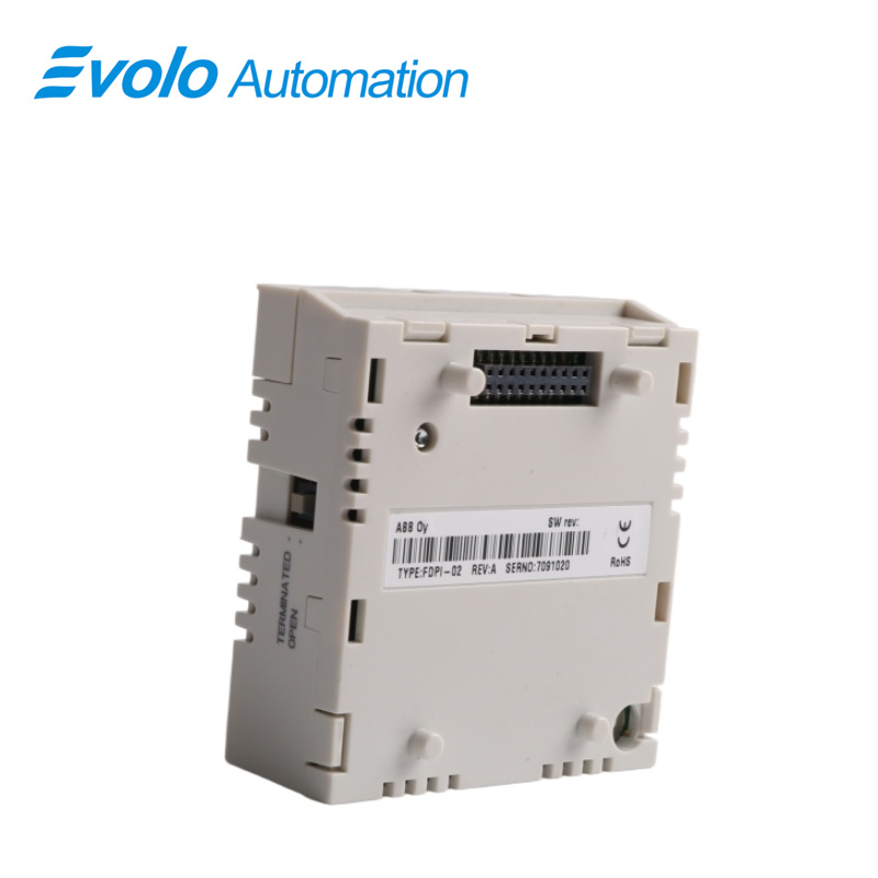
- Overview
- Specifications
- Description
- Applications
- Installation
- FAQ
- Recommended Products
Overview
Place of Origin: |
Sweden |
Brand Name: |
ABB |
Model Number: |
FDPI-02 |
Packaging Details: |
Original new Factory Sealed |
Delivery Time: |
5-7 days |
Payment Terms: |
T/T |
Supply Ability: |
In stock |
Specifications
|
Model: |
FDPI-02 |
|
Product Type: |
Diagnostics and Panel Interface Unit |
|
Dimensions: |
6.2x3.5x6.6 cm |
|
Weight: |
0.06 kg |
|
Protection Class: |
IP20 |
|
Input Phase: |
3-phase |
|
Input Voltage: |
480 V |
|
Frequency: |
60 Hz |
|
Power Factor: |
0.98 |
|
Max Output Current: |
2.9 A |
|
Operating Temperature Range: |
+0°C to +70°C |
|
Storage Temperature Range: |
-40°C to +70°C |
|
Relative Humidity: |
≤95% (non-condensing) |
|
Connectors: |
X1 (6-pin RJ-11), X2/X3 (RJ-45 shielded), X100/X101 (20-pin feed-through) |
|
Mounting Type: |
Panel interface mounting |
|
PCB Standard: |
UL recognized, conformal coated |
|
EMC Compliance: |
EN 61800-3:2004 |
|
Estimated Lifetime: |
20 years |
Description
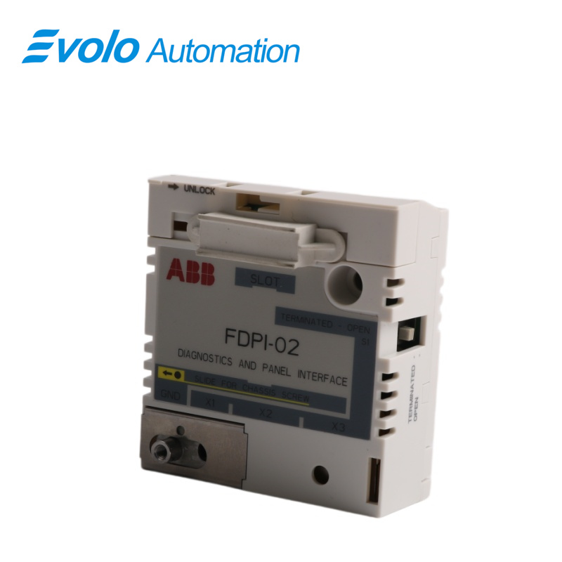
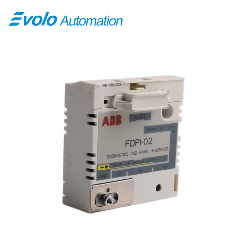
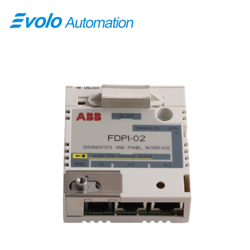
FDPI-02 diagnostics and panel interface is used for branching the RS-485 panel bus and chaining a control panel or PC tool to several drives. The interface unit provides a feed-through connection between a control unit and an F-type option module. It is compatible with the ZCU-…, BCU-… and UCU-… control units. The interface unit is installed in an option slot of the control unit. A small F-type option module can then be installed on top of the interface unit. The interface unit has one RJ-11 and two RJ-45 connectors. The RJ-11 connector is used for connecting the control unit. The RJ-45 connectors support a daisy chain bus for connecting a PC or a control panel (simultaneous control panel and PC communication is not allowed).
Applications
Automotive painting plants: Utilizing fiber optics for interference-free drive control in the complex electromagnetic environment of paint spraying lines.
Non-ferrous metal smelting plants: Providing remote monitoring of frequency converters in strong electric field environments, ensuring control signals are unaffected by high-frequency interference.
Paper processing plants: Synchronous control of multiple drive systems in large paper mills, guaranteeing real-time signal transmission over long distances.
Port machinery plants: Providing remote diagnostics and parameter backup for frequency converters in quay cranes and yard cranes.
Semiconductor manufacturing plants: Providing extremely low-noise communication links in precision power drive systems within cleanroom environments.
Installation
Installing the FDPI-02 onto the control unit:
1. Stop the drive and do the Electrical safety precautions in the drive safety instructions before you start the work.
2. On the FDPI-02 interface unit, move the slide for the chassis screw to the right.
3. Insert the interface unit into its designated option slot on the control unit (usually the option slot nearest to the panel bus connector of the control unit).
4. Fasten the unit with two screws to a torque of 0.8 N·m (7 lbf·in).
Installing an F-option module onto the installed FDPI-02:
1. Stop the drive and do the Electrical safety precautions in the drive safety instructions before you start the work.
2. On the interface unit, remove the dust seal (1a), move the slide for the chassis screw to the left (1b) and open the connector lock (1c) by sliding it to the right.
3. Install the option module onto the interface unit.
4. Close the connector lock (3a) by sliding it back to the left and fasten the module with the chassis screw (3b).
FAQ
Q: What is the FDPI-02?
A: It is a diagnostics and panel interface unit.
Q: Can a regular network patch cord be used instead for the FDPI-02?
A: No. It uses the proprietary DDCS fiber optic protocol, and its physical layer is completely different from Ethernet.
Q: Does the FDPI-02 require an independent external power supply?
A: No. It draws power directly from the inverter control panel interface; it's plug-and-play.
Q: Why can't the host computer detect the inverter after connecting the FDPI-02?
A: Please check if the TX (transmit) and RX (receive) pins of the fiber optic cable are crossed or incorrectly connected. This is the most common wiring error.
Q: Does the FDPI-02 support the ACS880 series inverters?
A: Yes. It is a common option for ACS880 to achieve fiber optic interconnection and NETA-21 remote monitoring.