EN
EN




- Overview
- Specifications
- Description
- Features
- Replacing Software
- FREQUENTLY ASKED QUESTIONS
- Recommended Products
Overview
Place of Origin: |
USA |
Brand Name: |
GE |
Model Number: |
DS200SVAAG1A DS200SVAAG1ACB |
Packaging Details: |
Original new Factory Sealed |
Delivery Time: |
5-7 days |
Payment Terms: |
T/T |
Supply Ability: |
In stock |
Specifications
|
Part Number: |
DS200SVAAG1A, DS200SVAAG1ACB |
|
Manufacturer: |
General Electric |
|
Series: |
Drive Control |
|
Product Type: |
Voltage Attenuator Board |
|
Power Supply Voltage: |
28 V dc |
|
Technology: |
Surface mount |
|
Operating Temperature: |
-30 to +65 degrees Celsius |
|
Size: |
15.9 cm high x 17.8 cm |
|
Country of Manufacturer: |
United States (USA) |
|
Terminals: |
SC1, SC2, SC3 |
Description
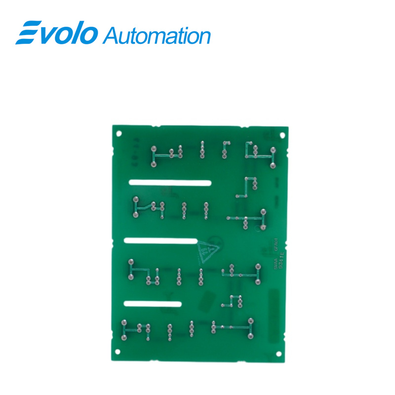
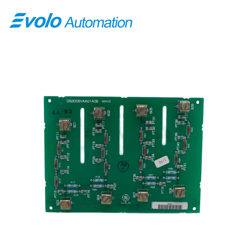
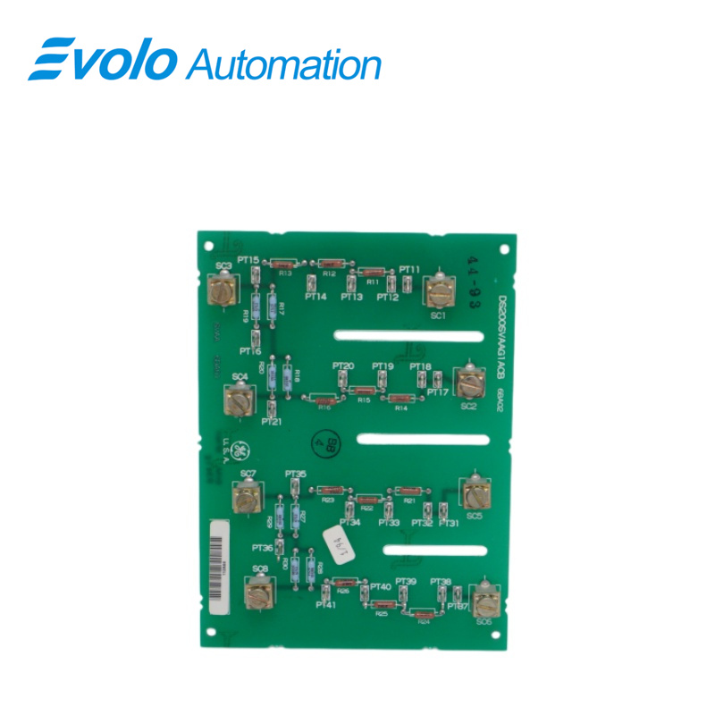
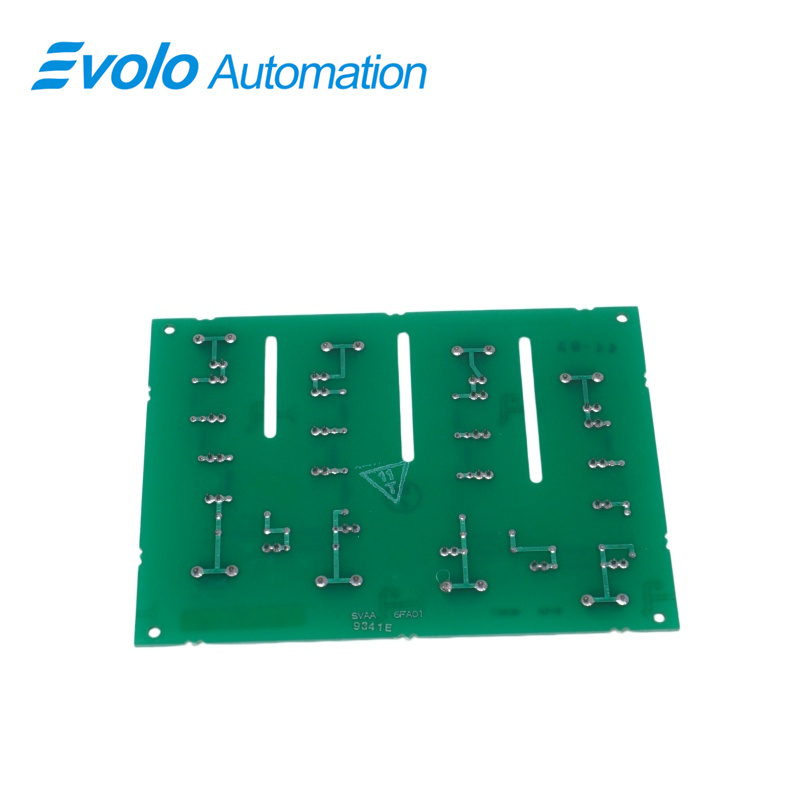
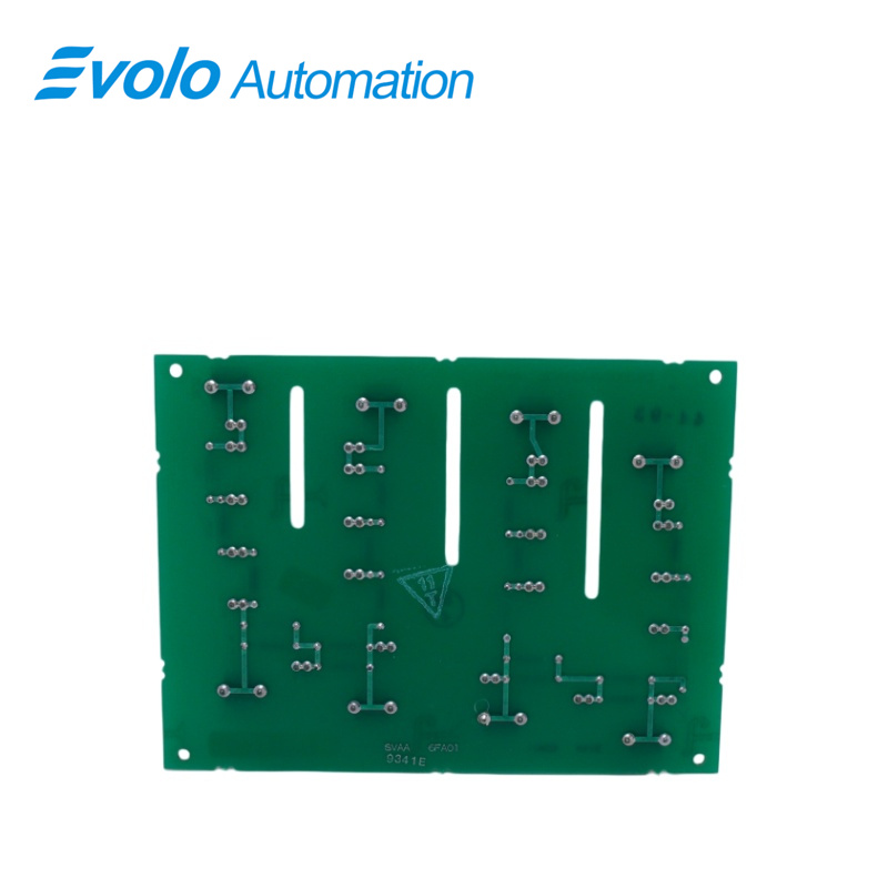
DS200SVAAG1A DS200SVAAG1ACB is a Voltage Attenuator Board designed and developed by GE.It is a part of General Electric Drive control system.A voltage attenuator board is a circuit board designed to attenuate or reduce the amplitude of an input voltage signal to a desired level.Attenuation refers to the process of reducing the strength of a signal without significantly affecting its waveform.In the context of electronic circuits, an attenuator is a device that can reduce the amplitude of a signal while maintaining its integrity.The voltage attenuator board typically contains one or more resistive voltage divider circuits.which use a combination of fixed resistors to divide the input voltage by a specific ratio.By selecting appropriate resistor values,the board can provide a specific level of attenuation that meets the requirements of a particular application.The attenuated signal can then be output to other circuits or devices.Voltage attenuator boards are commonly used in audio and video applications,as well as in measurement and testing equipment.They can be used to reduce the level of a high-amplitude audio or video signal to prevent distortion or to provide a more appropriate level for further processing.In testing applications,voltage attenuator boards can be used to reduce the voltage of a signal to a safe level for testing or analysis without damaging the test equipment.
Features
1.It has multiple test points and eight cable attachment terminals. The terminals on the board are given numbers that begin with the letter SC. The first three terminals,for example, are designated as SC1, SC2, and SC3.
2.If you suspect that the board isn't working or is having intermittent problems, the test points on the board can help. Only a qualified servicer with qualified testing equipment can use the test points. If you suspect a problem, however, it is best to first use the diagnostic tools available on the drive. The diagnostic tool will generate a report detailing the components and their performance. It can be used to identify problems or areas that can be improved
3.The drive features a control panel with a two-line display as well as a keyboard for selecting options and scrolling through menu options. There are two types of menu options.
4.Most are used to gain access to configuration areas for editing and viewing. The configuration defines the parameters that govern how the drive operates and can be changed via the control panel.Other menu options allow you to run the diagnostic tools.After the tool generates a report, you can save it to your laptop Or other device. You can save the file for later use, which may be useful for comparing diagnostic results after a repair is completed.
Replacing Software
1. Remove one of the old card's two EPROM chips (U6 or U7) and insert it into the appropriate socket on the new SLCC. When removing and inserting EPROMs, use the proper extraction/insertion tool to avoid component damage. To avoid memory chip damage, make sure the chips are properly oriented when inserting them into sockets
2. Repeat steps 1 and 2 for the remaining EPROMs.
3. Install new EPROMs if the failure symptoms that caused the card to be replaced persist.
FREQUENTLY ASKED QUESTIONS
Q: What is DS200SVAAG1A DS200SVAAG1ACB?
A: It is a Voltage Attenuator Board developed by General Electric.
Q: What are the cable attachment terminals on the DS200SVAAG1A DS200SVAAG1ACB Voltage Attenuator Board?
A: The board has eight cable attachment terminals, labeled SC1 through SC8. The first three terminals, SC1, SC2, and SC3, are used for attaching cables from sensors such as temperature sensors, pressure sensors, and speed sensors.
Q: What are the two types of menu options available on the control panel of DS200SVAAG1A DS200SVAAG1ACB?
A: The control panel features a two-line display and a keyboard. One type of menu option provides access to configuration areas for editing and viewing parameters that govern drive operation. The other type allows running diagnostic tools to generate performance reports on components, which can be saved for later use.
Q: What is the power supply voltage required for DS200SVAAG1A DS200SVAAG1ACB?
A: The board requires a 28 V DC power supply.
Q: What is the operating temperature range for DS200SVAAG1A DS200SVAAG1ACB?
A: The operating temperature range is -30°C to +65°C.
Q: What is the size of DS200SVAAG1A DS200SVAAG1ACB?
A: The board measures 15.9 cm in height by 17.8 cm in width.