EN
EN




- Overview
- Specifications
- Description
- Applications
- Features
- Troubleshooting
- FAQ
- Recommended Products
Overview
Place of Origin: |
USA |
Brand Name: |
Woodward |
Model Number: |
5466-425 |
Packaging Details: |
Original new Factory Sealed |
Delivery Time: |
5-7 days |
Payment Terms: |
T/T |
Supply Ability: |
In stock |
Specifications
|
Model |
5466-425 |
|
Product Name |
Analog I/O Module |
|
Dimensions |
2.4 × 24.6 × 26.1 cm |
|
Weight |
0.9 kg |
|
Signal Accuracy |
±0.1% Full Scale |
|
Analog Inputs |
24 × 0–5V (Channels 23/24 with reduced filtering) |
|
Analog Outputs |
8 × 4–20mA |
|
Compatibility |
For use with Dataforth FTM |
|
Operating Voltage |
24 VDC |
|
Update Time |
5 ms |
|
Mounting Type |
Plug-in standard slot board (hot-swap style) |
|
Front Panel |
Status LEDs included |
Description
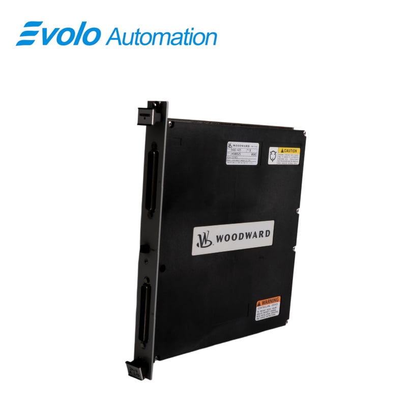
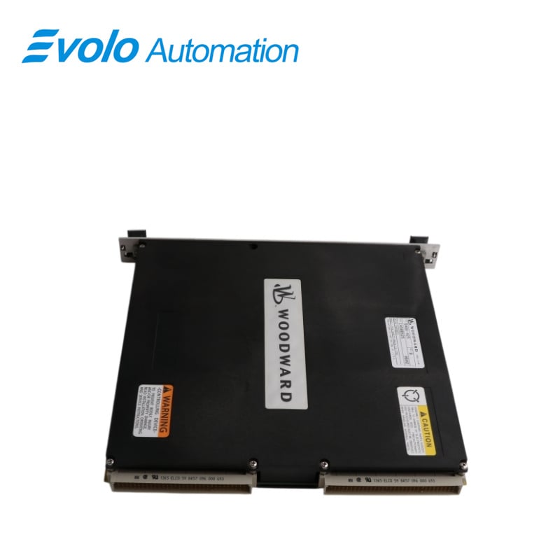
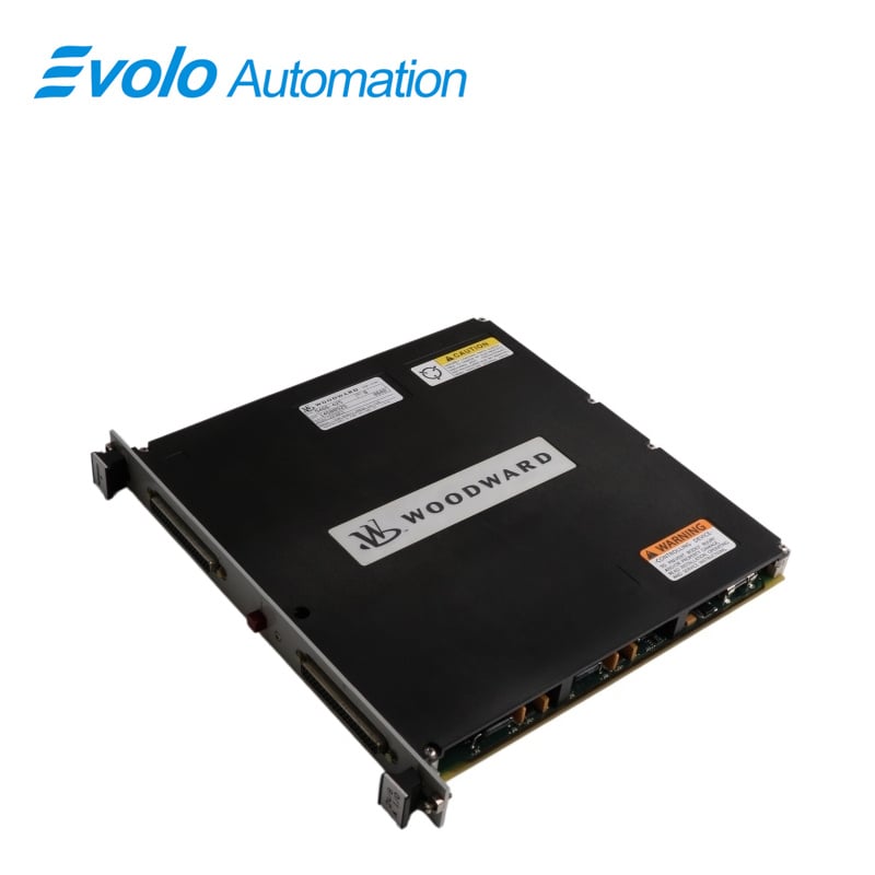
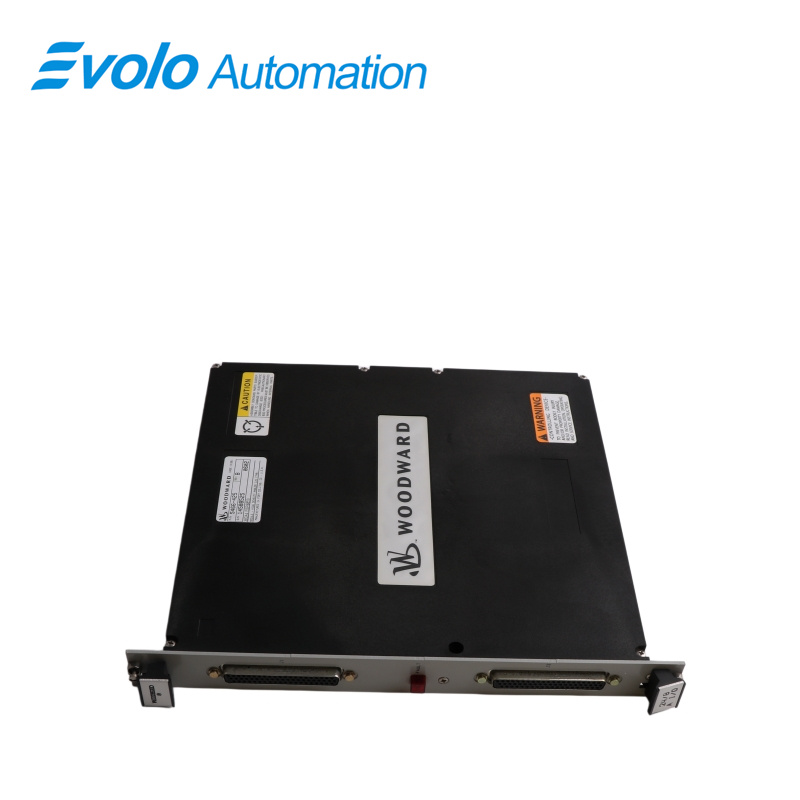
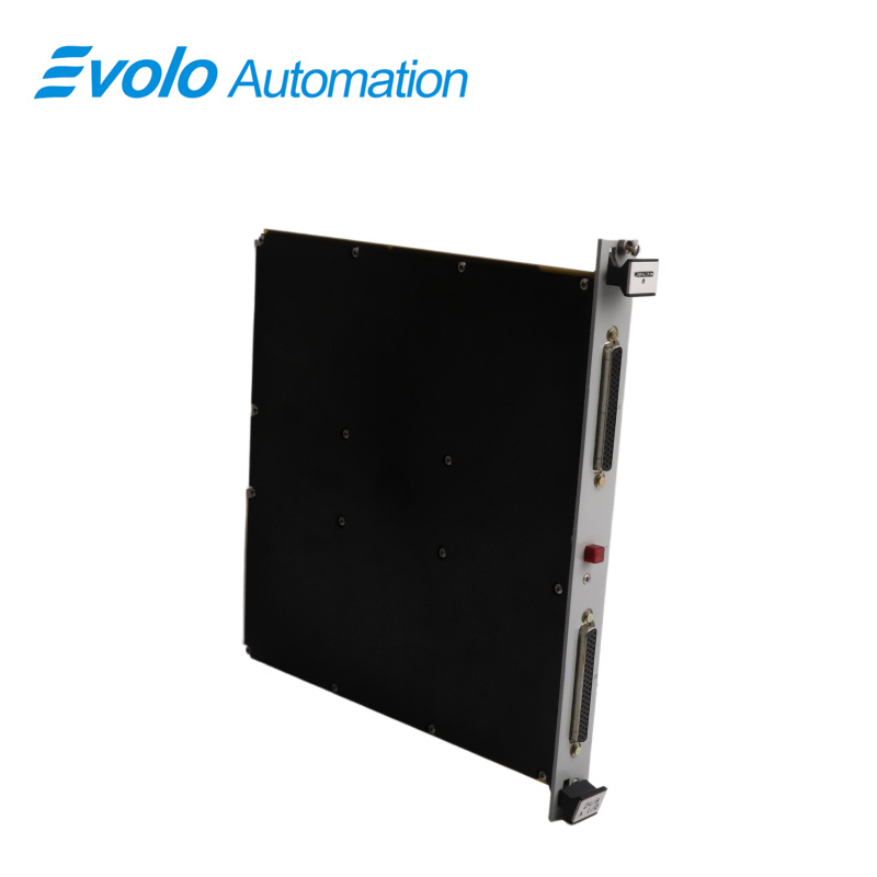
5466-425 is an Analog I/O Module developed by Woodward. This module is used to handle a high density of analog signals for monitoring and control of analog quantities. On the input side, this module can accommodate signals such as voltage, current, temperature, pressure, and other analog quantities. It provides reliable signal conditioning features such as amplification and filtering to optimize the signal quality and integrity.
Applications
Power Plants: Monitors boiler temperature and turbine pressure to ensure safe grid connection.
Petrochemical Plants: Connects remote flow and level meters for fast updates and pressure protection.
Steel Mills: Captures instant thickness changes in rolling control systems without delay.
Pulp & Paper Mills: Controls tension and dosing valves to maintain stable output quality.
Wastewater Treatment Plants: Collects multi-sensor data and controls pump speed for efficient automation.
Features
The maximum voltage input range can range between 4.975 and 5.025 Volts depending on the module,
The 24 channel analog inputs are divided into two banks, with data collected from channels 1 through 12 at 1.8 ms after the MFT tick and data collected from channels 13 through 24 at 3.7 ms after the MFT tick。
When using the 24/8 Analog FTM, set the Conf. input field to 1 when configuring the Al Combo block in GAR. This will allow the block to use the module factory calibration values for the 4-20 mA inputs on the 24/8 Analog Module, which were calibrated with 200 ohm internal resistors.
Troubleshooting
When the system is reset, a red Fault LED illuminates on each 24/8 Analog module.
The CPU activates the Fault LED during module initialization, which occurs after each CPU reset. The CPU then runs diagnostic routines built into the software on each module. If the diagnostic test fails, the LED remains illuminated or blinks. The LED turns off if the test is successful.
If the Fault LED on a module illuminates after diagnostics and initialization, the module may be faulty or in the incorrect slot.
FAQ
Q: What is the voltage input range of the 5466-425 module?
A: 4.975–5.025 V depending on configuration.
Q: How are analog inputs structured in the 5466-425 for data collection timing?
A: 24 channels split into two banks: CH1–12 sampled at 1.8 ms after MFT tick, CH13–24 at 3.7 ms.
Q: How many analog output channels (4–20 mA) does the 5466-425 include?
A: Includes 8 analog output channels of 4–20 mA.
Q: What mounting method does the 5466-425 use?
A: Uses plug-in standard slot board mounting (hot-swap style supported).
Q: What is the parameter update time of the 5466-425?
A: Update time is 5 ms.