EN
EN




- Overview
- Specifications
- Description
- IGPA Features
- Safety and Compliance
- System Features
- Frequently Asked Questions
- Recommended Products
Overview
Place of Origin: |
USA |
Brand Name: |
GE |
Model Number: |
IS200IGPAG2AED |
Packaging Details: |
Original new Factory Sealed |
Delivery Time: |
5-7 days |
Payment Terms: |
T/T |
Supply Ability: |
In stock |
Specifications
|
Part Number |
IS200IGPAG2AED |
|
Manufacturer |
General Electric |
|
Country of Manufacture |
United States of America (USA) |
|
Series |
EX2100 |
|
Product Type |
Gate Drive Power Supply Board |
|
Dimensions |
19 x 16.5 x 5 cm |
|
Weight |
0.38 kg |
|
Number of Plug Connectors |
8 |
|
Number of Terminal Connectors |
2 |
|
Inductor |
1 |
|
Electrolytic Capacitors |
4 |
|
Heatsinks |
6 (arranged in 2 rows) |
|
LED Indicators |
2 sets (each set: 1 amber + 1 green) on both sides of PCB |
|
Compliance |
EN 50081-2 (Generic Emission Standard) |
Description
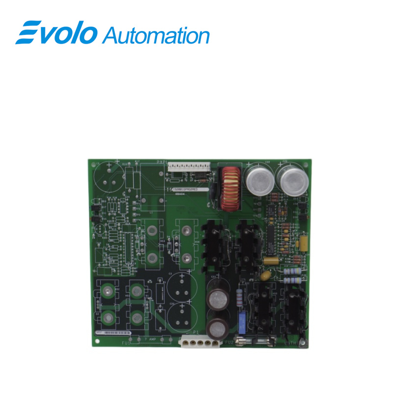
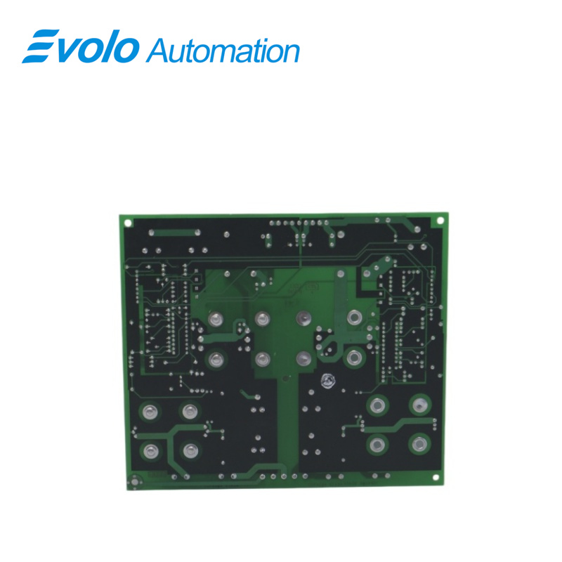
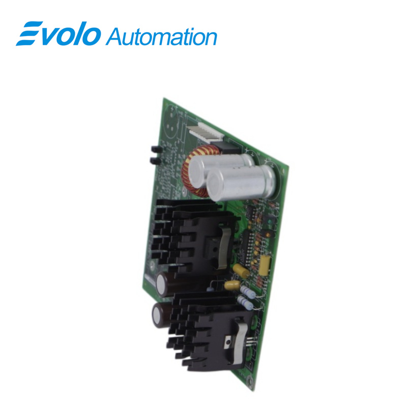
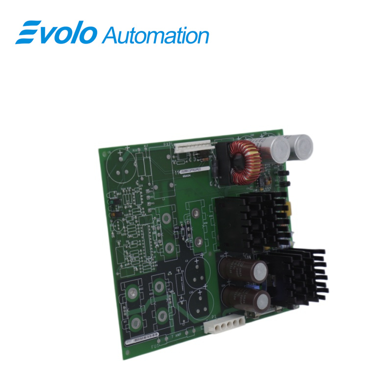
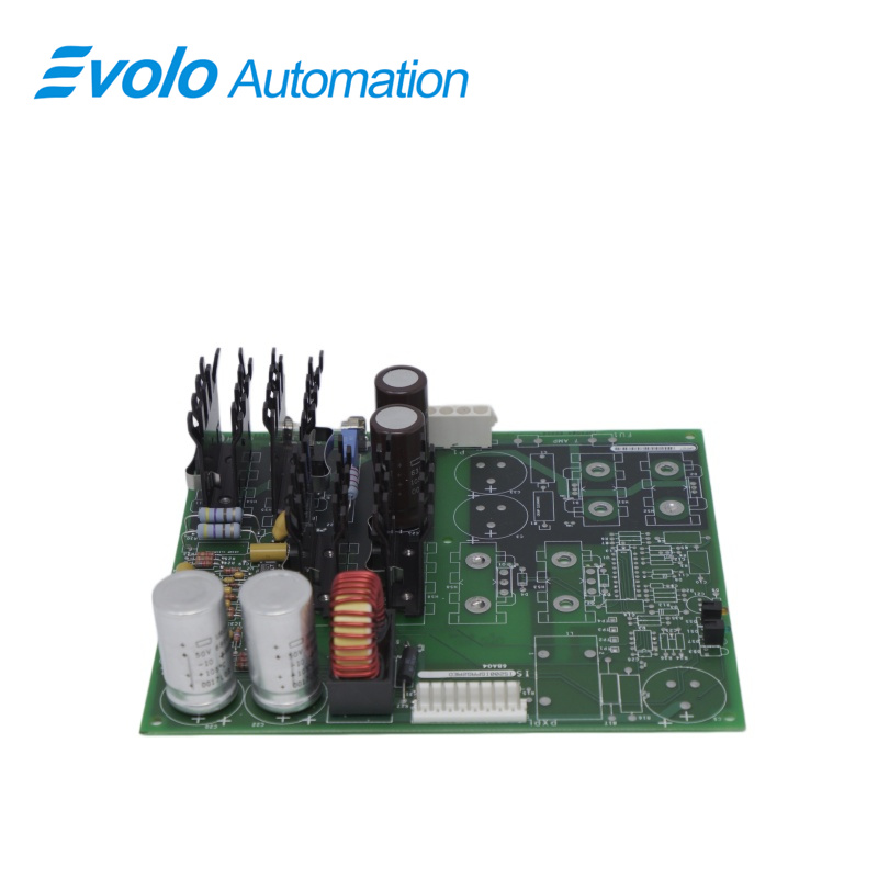
IS200IGPAG2AED is a Gate Drive Power Supply Board developed by GE. It is a part of EX2100 excitation system. It provide power supply functionalities to the gate drive, thereby enabling precise and controlled power delivery to the system's critical components. This board's design and functionalities are meticulously crafted to meet the stringent performance requirements and operational demands of the ExX2100 excitation system.
IGPA Features
1.LED Indicators: Features two sets of LEDs positioned on opposite sides. Each set includes one amber LED and one green LED, providing visual status indicators essential for monitoring operational states.
2.Right Side Configuration: The right side of the board primarily hosts the LEDs, several terminal connectors, and a single vertical 9-pin male header connector. It includes outlined positions for additional components that are not populated on the board. Inductors and Capacitors.
Safety and Compliance
1 EN 50081-2: Generic Emissions Standard
2 EN 50082-2:1994: Generic Immunity Industrial Environment
3 EN 50178: Gas Contaminants codes
4 EN 50178:1994: Elevation code
5 IEC529:1989-11 (IP-20): Dust Contaminants code
System Features
1 The exciter stands as a versatile and adaptable modular system capable of diverse configurations to cater to various output currents and ensure multiple levels of system redundancy. This adaptability facilitates assembling the exciter system in a manner that suits specific requirements. Notably, this system offers a spectrum of available output currents and several redundancy levels, with options that encompass power drawn from potential, compound, or auxiliary sources.
2 These flexible configurations encompass choices such as employing single or multiple bridges, warm backup bridges, as well as the availability of simplex or redundant controls. Such variability allows for customization based on operational needs and preferences, ensuring a tailored approach to system design. An illustrative overview of the turbine generator excitation system is provided in Figure 1-1, depicting the architecture's key components and their interconnections. To power the exciter, there are two primary sources: either from a power potential transformer linked to the generator terminals or via an excitation transformer connected to an auxiliary bus.
3 Feedback mechanisms within the exciter system rely significantly on two primary inputs: generator line current and stator output voltage. These inputs serve as pivotal feedback parameters, guiding and influencing the exciter's operations. In response, the exciter regulates its output in terms of DC voltage and current, effectively controlling the exciter field.
4 An additional layer of sophistication in the exciter system architecture involves its compatibility with Ethernet LAN (Unit Data Highway) communication. This communication capability allows seamless interaction and integration with other GE equipment, including the GE Control System Toolbox (commonly referred to as "toolbox") used for configuration purposes, the turbine control system, the LCI Static Starter, and the HMI (operator interface).
5 This compatibility with an Ethernet LAN facilitates streamlined communication and coordination between the exciter system and other integral components within the larger operational framework. It enables efficient data exchange, thereby enhancing overall system functionality and performance. This interconnectedness signifies a holistic approach to system design, emphasizing interoperability and collaboration among various elements within the broader operational setup.
Frequently Asked Questions
Q: What is IS200IGPAG2AED?
A: It is a Gate Drive Power Supply Board developed by GE under the EX2100 series.
Q: What power options does the exciter system offer of IS200IGPAG2AED?
A: It supports power from potential, compound, or auxiliary sources, allowing configurations with single or multiple bridges, warm backup bridges, and simplex or redundant controls.
Q: How is power supplied to the exciter of IS200IGPAG2AED?
A: Power is drawn either from a power potential transformer connected to the generator terminals or from an excitation transformer linked to an auxiliary bus.
Q: What are the key feedback mechanisms for the exciter of IS200IGPAG2AED?
A: Primary feedback sources include generator line current and stator output voltage. The exciter system adjusts DC voltage and current to control the exciter field based on this feedback.