EN




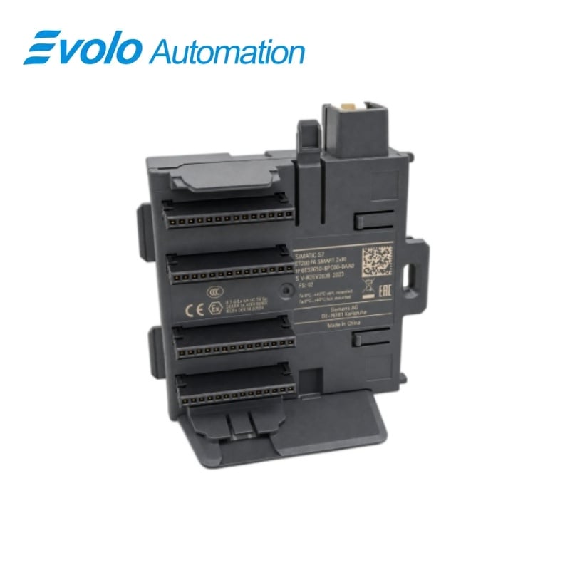
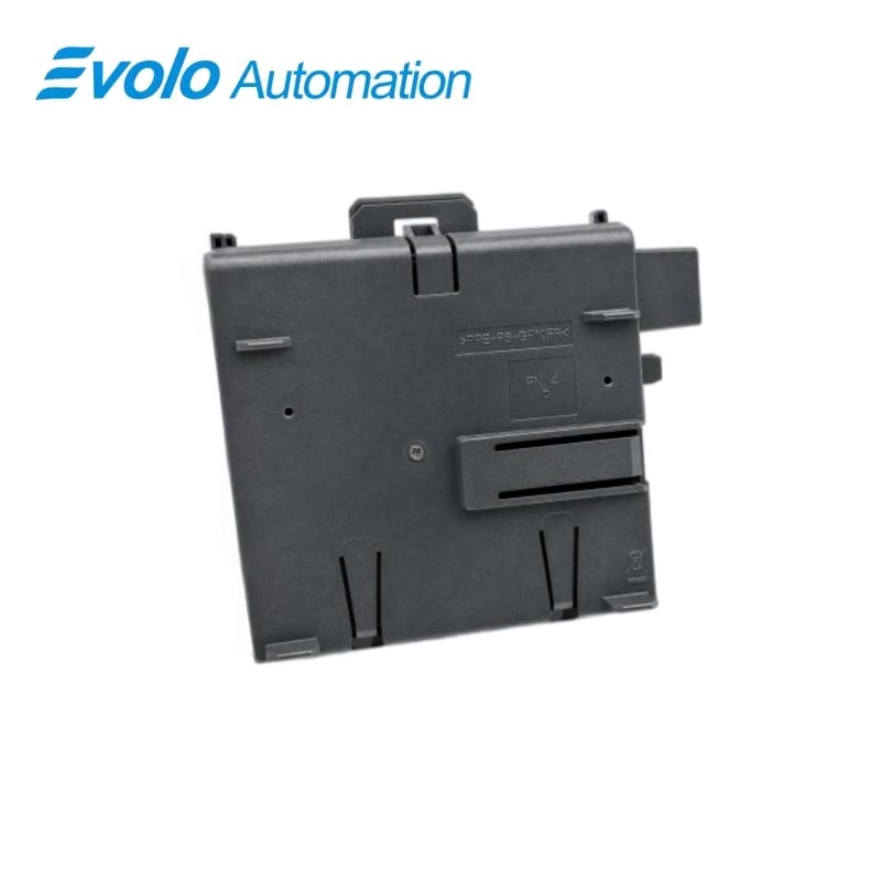
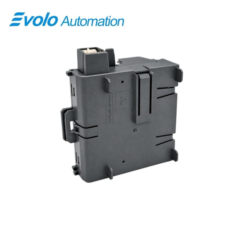
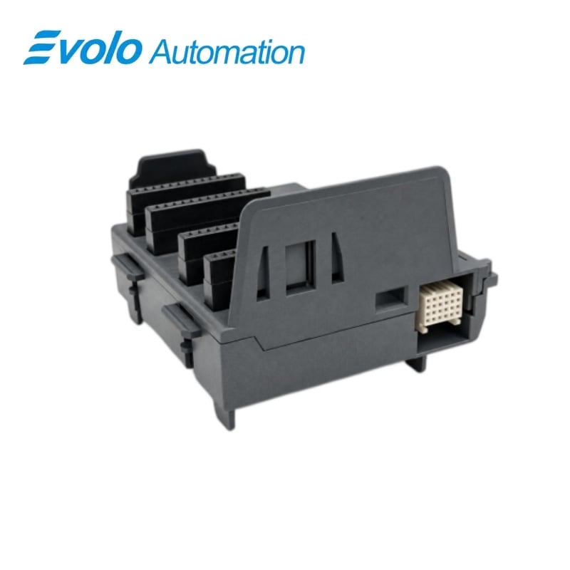
Siemens 6ES7650-8PA00-0AA0 ET 200PA SMART BM PS/IM Active Bus Module
Manufacturer: Siemens
Condition: Brand New
Lead Time: In Stock
Origin: Germany
Warranty: 12 Months
Email: [email protected]
whatsApp: +86-18150117685
- Overview
- Hot Selling Models
- Recommended Products
Overview
- Use one IM 650 for the non-redundant arrangement.
- A redundant pair of IM 650 modules requires the separate BM IM/IM base.
- Install the active bus base with the station de-energized.
- Place the power supply and IM 650 on the left of a horizontal station or at the bottom of a vertical station.
- Keep all modules on the same mounting rail and within the 12-I/O-module station limit.
- Fit the supplied bus module cover at the rack end and separately ordered backplane covers at empty slots.
6ES7650-8PA00-0AA0 ET 200PA SMART BM PS/IM Active Bus Module
The active PS/IM base for a PS 307 2 A power supply and one IM 650 interface module, supplied with the bus module cover.
At a Glance
| Brand | Siemens |
|---|---|
| Model | 6ES7650-8PA00-0AA0 |
| Product Type | BM PS/IM active bus base |
| Core Function | Keeps the station backplane available during module servicing |
| Application | Non-redundant ET 200PA SMART interface arrangements |
Single-interface station
One IM 650 is used for the non-redundant station arrangement.
PS/IM positions
The base accommodates a PS 307 2 A power supply and the interface module.
Included end cover
The bus module cover is included with the PS/IM base.
Product Overview
6ES7650-8PA00-0AA0 forms the active PS/IM foundation for a non-redundant ET 200PA SMART station.
The base is intended for a PS 307 2 A power supply and one IM 650, while the active backplane permits the remaining modules to stay reachable when a module is absent; a bus module cover is supplied with the base.
Key Functions
Support the non-redundant interface arrangement
The PS/IM base provides the arrangement for one IM 650 together with the PS 307 2 A supply.
Maintain the active backplane connection
The active bus structure supports the station module-replacement arrangement without breaking access to the other modules.
Provide rack-end protection
The supplied bus module cover closes the final active bus module after the rack is assembled.
Official Specifications
| Mounting positions | One PS 307 2 A supply and one IM 650 interface module |
|---|---|
| Included cover | One bus module cover |
| Dimensions (W × H × D) | 97 × 92 × 30 mm |
| Approximate weight | 111 g |
| Permissible ambient temperature, horizontal assembly | 0 to 60 °C |
| Permissible ambient temperature, vertical assembly | 0 to 40 °C |
| Degree of protection, ET 200PA SMART assembly | IP20 |
| Mechanical locking | Inter-module latches and a mounting-rail lock |
Frequently Asked Questions
Is 6ES7650-8PA00-0AA0 the correct base for two redundant IM 650 modules?
A two-IM redundant arrangement uses the BM IM/IM base instead of the single-IM PS/IM base.
Which power-supply size is paired with 6ES7650-8PA00-0AA0?
The PS/IM arrangement accommodates a PS 307 rated at 2 A.
Does 6ES7650-8PA00-0AA0 include the final bus-module cover?
The PS/IM base is supplied with a bus module cover.
Must spare-slot covers be ordered separately from 6ES7650-8PA00-0AA0?
Backplane bus covers for unoccupied module slots are ordered separately.
Where should the power supply and IM 650 on 6ES7650-8PA00-0AA0 sit in a vertical rack?
The power supply and interface module belong at the bottom of a vertical station.
Can an ET 200PA SMART using 6ES7650-8PA00-0AA0 be extended to another rack with interface modules?
The ET 200PA SMART station must remain on one mounting rail and cannot use interface modules to connect additional racks.
How is 6ES7650-8PA00-0AA0 engaged before the adjacent I/O bus bases are fitted?
Hook the lower edge into the designated rail, press the base into place and slide it left to the latched position.