EN




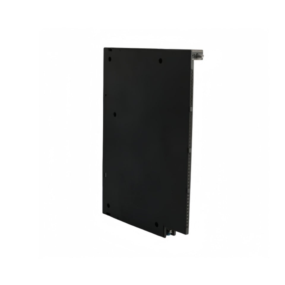
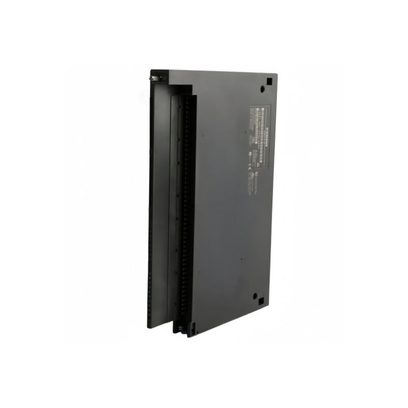
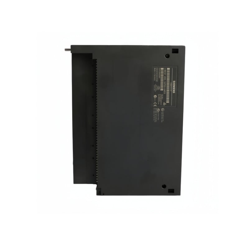
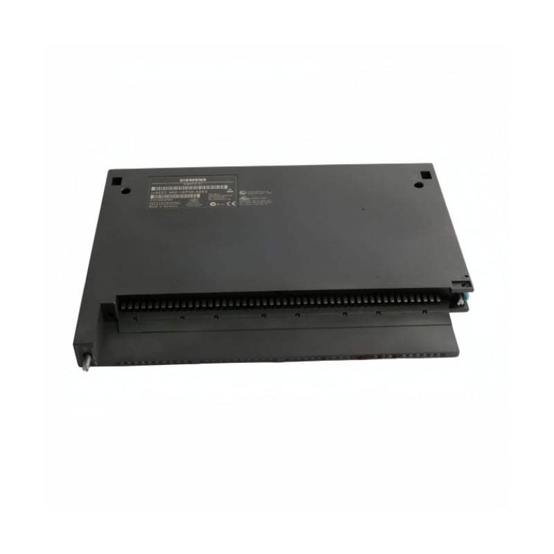
Siemens SIMATIC S7-400 FM 450-1 Counter Module 6ES7450-1AP00-0AE0
Manufacturer: Siemens
Condition: Brand New
Lead Time: In Stock
Origin: Germany
Warranty: 12 Months
Email: [email protected]
whatsApp: +86-18150117685
- Overview
- Product Overview
- Key Functions
- Official Specifications
- Frequently Asked Questions
- Compatibility & Ordering Notes
- Hot Selling Models
- Recommended Products
Overview
Siemens · SIMATIC S7-400 Function Modules
6ES7450-1AP00-0AE0 SIMATIC S7-400 FM 450-1 Counter Module
The Siemens SIMATIC S7-400 FM 450-1 is a two-channel counter module for high-speed counting with 5 V RS-422 or 24 V encoder signals, integrated digital inputs and direct digital outputs.
At a Glance
| Brand | Siemens |
|---|---|
| Model | 6ES7450-1AP00-0AE0 |
| Product Type | Two-channel high-speed counter module |
| Core Function | Processes encoder pulses and gate signals independently of the CPU scan for high-speed counting tasks |
| Application or Compatible Series | SIMATIC S7-400 systems requiring dedicated high-frequency counting and direct response outputs |
Exact Identification
Match 6ES7450-1AP00-0AE0 character by character and confirm the FM 450-1 two-channel counter-module designation.
Encoder Arrangement
Confirm each channel uses the correct 5 V RS-422 or 24 V encoder wiring and input-filter setting.
Configuration Check
Preserve the STEP 7 hardware configuration, addresses, channel parameters, gate logic and output behavior.
Product Overview
The Siemens SIMATIC S7-400 FM 450-1 is a two-channel counter module for high-speed counting with 5 V RS-422 or 24 V encoder signals, integrated digital inputs and direct digital outputs.
Two independent counting channels support continuous, single and periodic counting with a 32-bit counting width. Each channel accepts 5 V incremental encoders with an RS-422 interface or supported 24 V encoder and pulse signals. Integrated gate inputs, protected P-switch outputs, status LEDs and configurable interrupts support responsive machine control and troubleshooting.
Key Functions
Dual High-Speed Counting
Two independent counting channels support continuous, single and periodic counting with a 32-bit counting width.
Flexible Encoder Inputs
Each channel accepts 5 V incremental encoders with an RS-422 interface or supported 24 V encoder and pulse signals.
Direct Control and Diagnostics
Integrated gate inputs, protected P-switch outputs, status LEDs and configurable interrupts support responsive machine control and troubleshooting.
Official Specifications
| Counting Channels | 2 |
|---|---|
| Counting Width | 32 bit |
| Maximum Frequency with 5 V Encoders | 500 kHz |
| Maximum Frequency with 24 V Encoders | 200 kHz; 20 kHz selectable |
| 5 V Counter Input Interface | RS-422 differential |
| 5 V Encoder Supply | 5.2 V DC ±2%; maximum 300 mA per channel |
| Auxiliary Voltage 1L+/1M | 24 V DC |
| Auxiliary Voltage Range | 20.4 to 28.8 V DC static; 18.5 to 30.2 V DC dynamic |
| Load Voltage 2L+/2M | 24 V DC; electrically isolated from other voltages |
| Load Voltage Range | 20.4 to 28.8 V DC static; 18.5 to 30.2 V DC dynamic |
| Digital Inputs | 6 total; three 24 V inputs per counter |
| Digital Input Filter Delays | 1 µs or 15 µs selectable |
| Digital Outputs | 4 P-switch outputs; two per counter |
| Maximum Digital Output Load | 0.5 A per output; overload and short-circuit protected |
| Maximum 5 V Backplane Current | Approximately 300 mA |
| Module Power Loss | Approximately 6 W |
| Status and Fault Indication | 14 green status LEDs and 2 red fault LEDs |
| Dimensions (W × H × D) | 25 × 290 × 210 mm |
| Approximate Weight | 650 g |
Frequently Asked Questions
Which encoder interfaces can be connected to 6ES7450-1AP00-0AE0?
Use a 5 V incremental encoder with an RS-422 interface or a supported 24 V incremental, directional or pulse encoder.
What is the maximum counting frequency of 6ES7450-1AP00-0AE0?
The limit is 500 kHz for 5 V encoder signals and 200 kHz for 24 V signals when the high-frequency filter is selected.
How are the two channels of 6ES7450-1AP00-0AE0 used?
Each channel processes its own encoder, gate inputs and response outputs for an independently configured counting task.
Which supply circuits are required for 6ES7450-1AP00-0AE0?
Provide the specified 24 V auxiliary supply and a separate 24 V load supply within their permitted voltage ranges.
Can 6ES7450-1AP00-0AE0 switch control loads directly?
Four protected P-switch outputs are available, with two assigned to each channel and a maximum load of 0.5 A per output.
What should be preserved before replacing 6ES7450-1AP00-0AE0?
Save the STEP 7 hardware configuration, channel parameters, addresses, encoder wiring and gate or output assignments.
Which indicators help diagnose 6ES7450-1AP00-0AE0?
Fourteen green LEDs show channel and I/O status, while two red LEDs identify internal and external fault conditions.
Compatibility & Ordering Notes
Compatibility Checklist
- Use the module only in a compatible SIMATIC S7-400 configuration.
- Match each installed encoder to the configured 5 V RS-422 or 24 V input type.
- Restore the original channel parameters, addresses, gate logic and digital-output behavior before commissioning.