EN




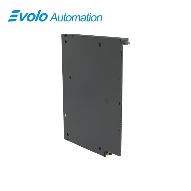
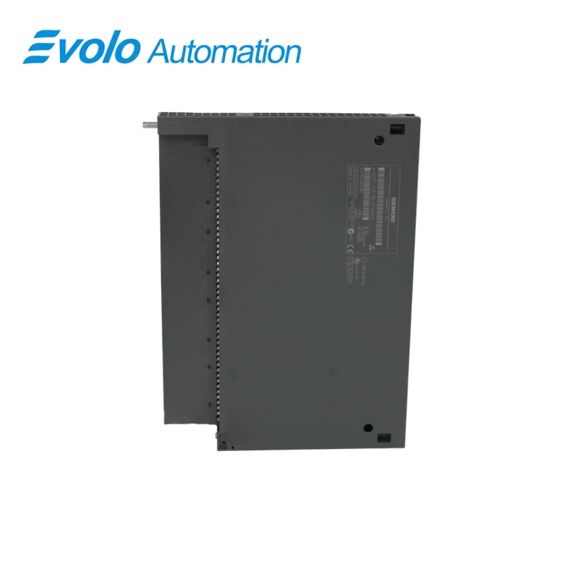
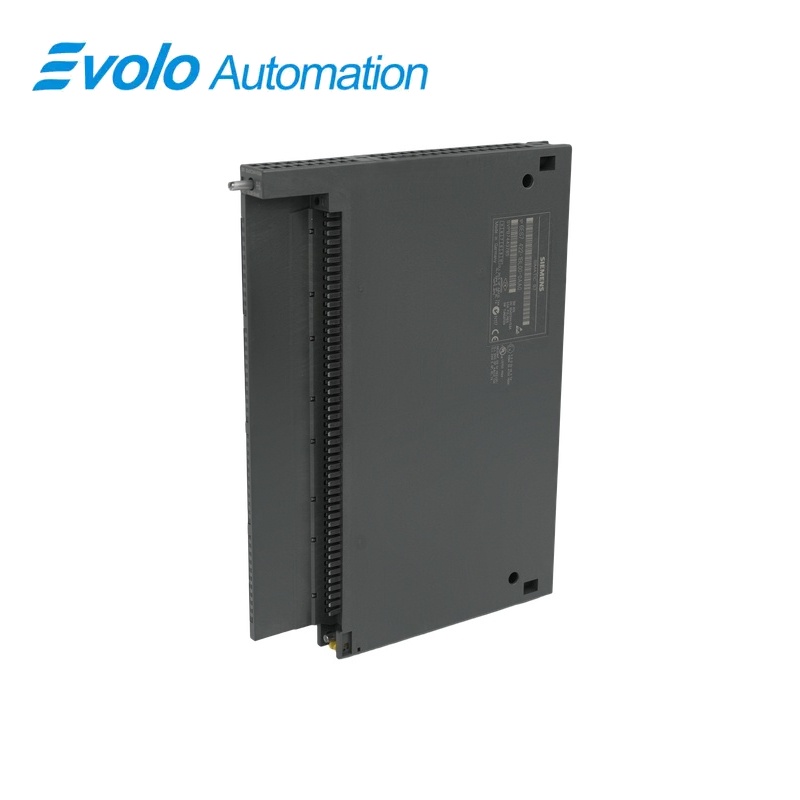
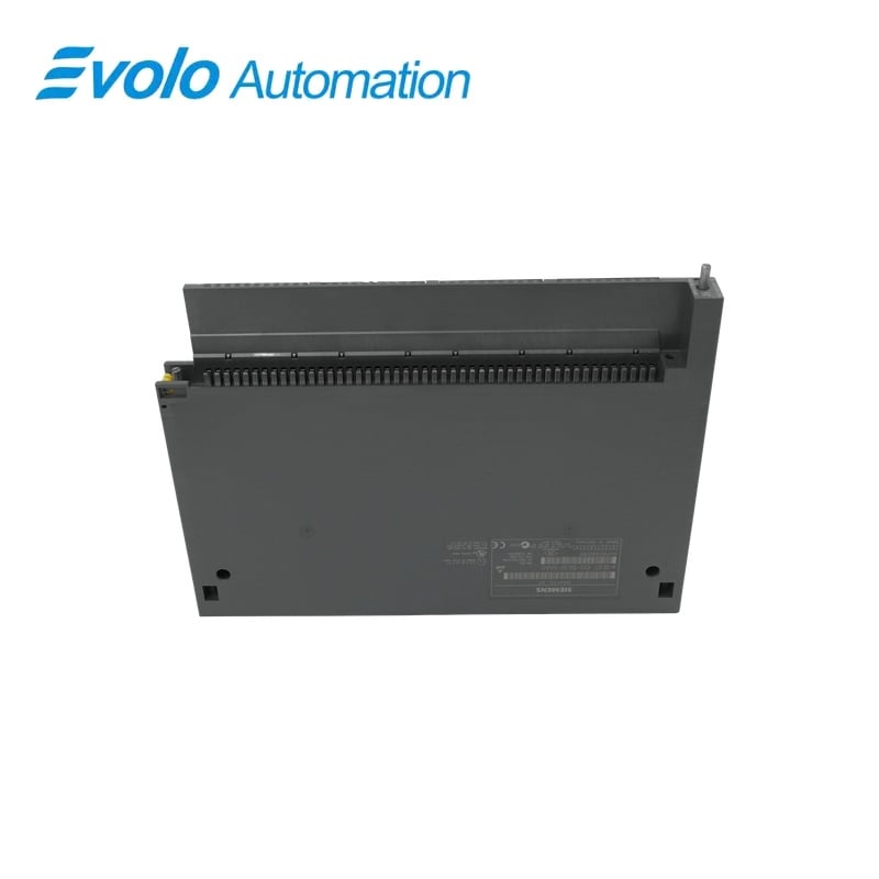
Siemens 6ES7421-1BL01-0AA0 S7-400 SM 421 32-Channel Digital Input Module
Manufacturer: Siemens
Condition: Brand New
Lead Time: In Stock
Origin: Germany
Warranty: 12 Months
Email: [email protected]
whatsApp: +86-18150117685
- Overview
- Hot Selling Models
- Recommended Products
Overview
- Use the 24 V DC input arrangement of the S7-400 station.
- Keep sensor quiescent current within the specified limit.
- Account for a 1.2–4.8 ms delay on both input transitions.
- Use the green LEDs for channel-state checks rather than module fault diagnosis.
6ES7421-1BL01-0AA0 S7-400 SM 421 32-Channel Digital Input Module
A 25 mm-wide SM 421 with 32 simultaneous inputs, fixed millisecond response and optically separated backplane integration.
At a Glance
| Brand | Siemens |
|---|---|
| Model | 6ES7421-1BL01-0AA0 |
| Product Type | Digital input signal module |
| Core Function | Parallel monitoring of discrete field contacts |
| Application | SIMATIC S7-400 input racks |
32 input points
All 32 inputs can be active simultaneously.
Fixed response window
Both switching transitions have an input delay of 1.2–4.8 ms.
Local state indication
Green input LEDs show channel states without a module diagnostic function.
Product Overview
6ES7421-1BL01-0AA0 brings 32 discrete input signals into a SIMATIC S7-400 rack. The SM 421 accepts rated 24 V DC signals with an IEC 61131 type-1 input characteristic and supports all channels being active simultaneously.
The input group is isolated from the backplane, while its channels do not provide individual galvanic separation. Fixed input delays and sensor leakage-current limits are relevant when replacing an existing module or selecting field sensors.
Key Functions
Read a full bank of field contacts
The module acquires 32 input states and permits every input to be active at the same time.
Reject signals outside the logic ranges
The logic-0 range is −30 to +5 V DC, while logic 1 requires +13 to +30 V DC.
Support extended field wiring
Maximum field-cable lengths are 1,000 m with shielding and 600 m without shielding.
Official Specifications
| Input capacity | 32 digital inputs, all simultaneously active |
|---|---|
| Input characteristic | IEC 61131 type 1 |
| Rated input voltage | 24 V DC |
| Logic voltage ranges | Signal 0: −30 to +5 V DC; signal 1: +13 to +30 V DC |
| Typical signal-1 current | 7 mA |
| Maximum signal-0 quiescent current | 1.3 mA |
| Input delay for both transitions | 1.2–4.8 ms |
| Maximum two-wire sensor quiescent current | 1.5 mA |
| Maximum cable length | 1,000 m shielded; 600 m unshielded |
| Maximum backplane current | 20 mA from 5 V DC |
| Typical power loss | 6 W |
| Input isolation arrangement | Group of 32 channels; no individual channel isolation; isolation from backplane |
| Insulation type-test voltage | 500 V AC or 707 V DC |
| Status and diagnostics | Green input-state LEDs; no diagnostic function |
| Dimensions and approximate weight | 25 × 290 × 210 mm (W × H × D); 500 g |
Frequently Asked Questions
Can all channels on 6ES7421-1BL01-0AA0 remain active at once?
All 32 inputs may be active simultaneously.
Will a 10 V field signal reliably switch on 6ES7421-1BL01-0AA0?
The specified logic-1 voltage range begins at 13 V DC.
How quickly does 6ES7421-1BL01-0AA0 recognize either edge of an input signal?
The input delay is between 1.2 and 4.8 ms for both rising and falling transitions.
Are the input references on 6ES7421-1BL01-0AA0 individually isolated?
The channels form one group of 32 and are not individually isolated from each other.
Can I use the green LEDs on 6ES7421-1BL01-0AA0 as fault-diagnostic indicators?
The green LEDs indicate input states and the module has no diagnostic function.
What cable length can an unshielded sensor circuit use with 6ES7421-1BL01-0AA0?
The maximum permitted unshielded cable length is 600 m.
How much 5 V backplane current should I budget for 6ES7421-1BL01-0AA0?
Allow up to 20 mA from the 5 V DC backplane.