EN




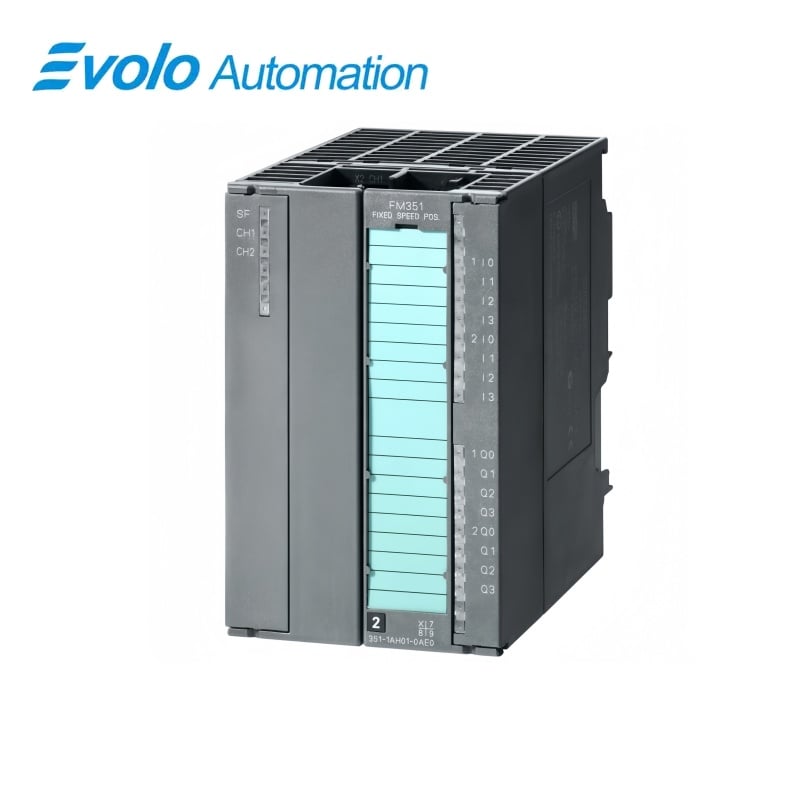
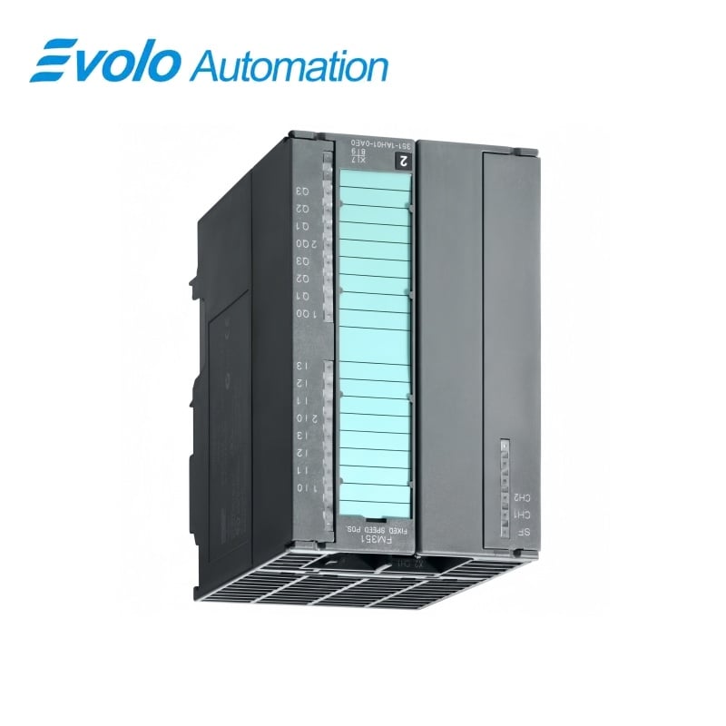
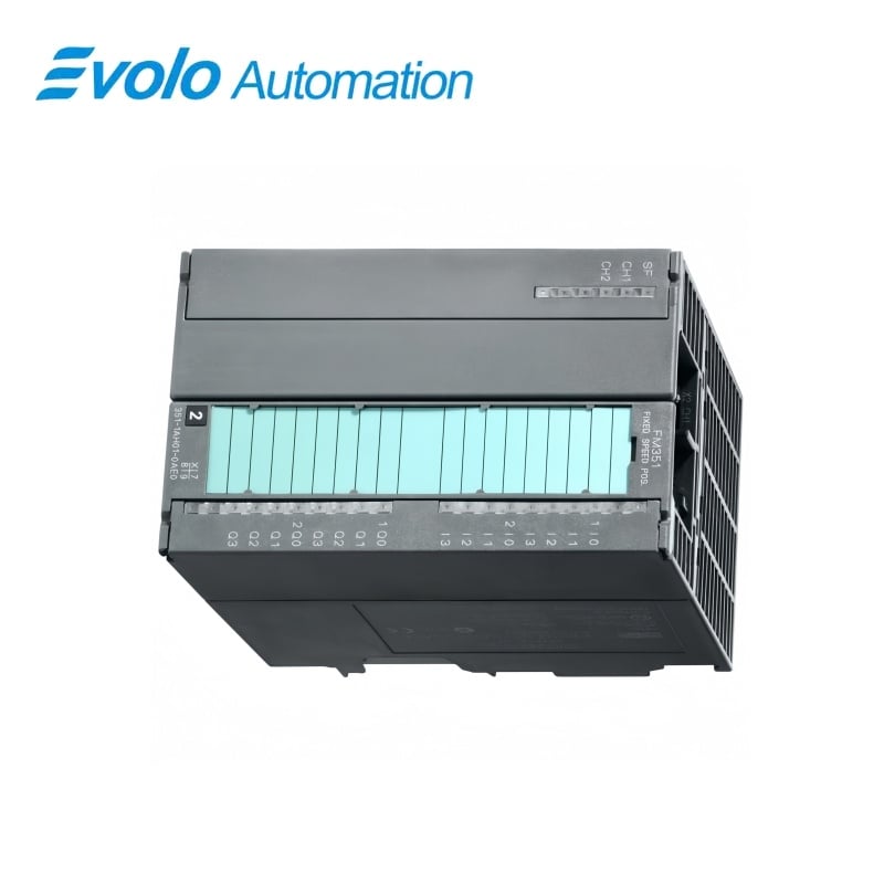
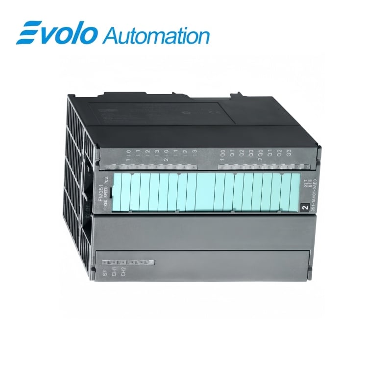
Siemens SIMATIC S7-300 6ES7353-1AH01-0AE0 FM 353
Manufacturer: Siemens
Condition: Brand New
Lead Time: In Stock
Origin: Germany
Warranty: 12 Months
Email: [email protected]
whatsApp: +86-18150117685
- Overview
- Product Overview
- Key Functions
- Official Specifications
- Frequently Asked Questions
- Compatibility & Ordering Notes
- Hot Selling Models
- Recommended Products
Overview
SIMATIC S7-300 FUNCTION MODULE
6ES7353-1AH01-0AE0 FM 353 Stepper Drive Positioning Module
S7-300 function module for positioning a stepper-motor axis with pulse frequencies up to 200 kHz.
At a Glance
| Brand | Siemens |
|---|---|
| Model | 6ES7353-1AH01-0AE0 |
| Product Type | Stepper positioning function module |
| Core Function | Controls point-to-point motion and traversing profiles for a stepper-motor axis |
| Application or Compatible Series | SIMATIC S7-300 and supported ET 200M configurations |
Axis Assignment
Confirm that the installed axis uses a stepper motor and the FM 353 pulse interface.
Signal Wiring
Record reference cams, message input, digital outputs and field-supply wiring before exchange.
Project Retention
Archive the STEP 7 hardware configuration and positioning parameters before removal.
Product Overview
The FM 353 is a positioning function module for stepper-motor applications that require programmed motion sequences and high clock-pulse rates.
It supports module replacement without a programming device and is engineered with STEP 7 using the supplied configuration package.
Key Functions
Stepper Pulse Generation
Outputs the configured pulse and direction signals for stepper-drive positioning.
Positioning Modes
Supports point-to-point moves, traversing programs, jogging and open-loop control.
Machine Signal Handling
Uses digital inputs and outputs for reference cams, start/stop control, auxiliary functions and position messages.
Official Specifications
| Minimum Engineering Software | STEP 7 V3.1 with configuration package |
|---|---|
| Rated Supply Voltage | 24 V DC |
| Permissible Supply Range | 20.4 to 28.8 V DC |
| Maximum Current Consumption | 300 mA |
| Digital Inputs | 4 plus 1 message-signal input |
| Input Level for Logic 0 | -3 to +5 V |
| Input Level for Logic 1 | 11 to 30 V |
| Digital Outputs | 4 |
| Output Voltage for Logic 1 | Supply voltage minus 3 V |
| Rated Output Current at 40 °C | 0.5 A per output; 2 A total |
| Permissible Output Current at 40 °C | 5 mA to 0.6 A |
| Maximum Lamp Load | 5 W |
| Rated Output Current at 60 °C | 0.1 A per output; 0.4 A total |
| Permissible Output Current at 60 °C | 5 mA to 0.12 A |
| Resistive-Load Switching Frequency | Up to 100 Hz |
| Inductive-Load Switching Frequency | Up to 0.25 Hz |
| Open-Loop Frequency Range | 0 to 200,000 Hz |
| Net Weight | 0.55 kg |
Official source: Siemens official technical data for 6ES7353-1AH01-0AE0.
Frequently Asked Questions
Which drive type is 6ES7353-1AH01-0AE0 intended to control?
The module is designed to position one stepper-motor axis through pulse and direction signals.
What supply should I prepare for 6ES7353-1AH01-0AE0?
Provide a 24 V DC field supply within the permitted 20.4 to 28.8 V range.
Which engineering package is required for 6ES7353-1AH01-0AE0?
Use STEP 7 V3.1 or a compatible later environment together with the FM 353 configuration package.
How many field inputs are available on 6ES7353-1AH01-0AE0?
The module provides four digital inputs plus a separate message-signal input.
What pulse-frequency limit applies to 6ES7353-1AH01-0AE0?
The open-loop frequency command can be set from 0 to 200,000 Hz.
Can 6ES7353-1AH01-0AE0 be replaced without a programming device?
Yes, the product is designed to support module exchange without a programming device when the stored project and parameters are available.
What should I record before rewiring 6ES7353-1AH01-0AE0?
Document the stepper-drive pulse connection, digital I/O assignment, reference cams and field-supply polarity before removal.
Compatibility & Ordering Notes
Compatibility Checklist for 6ES7353-1AH01-0AE0
- Match the complete FM 353 article and installed firmware level.
- Confirm the stepper-drive pulse and direction interface.
- Back up STEP 7 hardware data and positioning parameters.
- Verify 24 V DC supply polarity and all digital I/O assignments.