EN




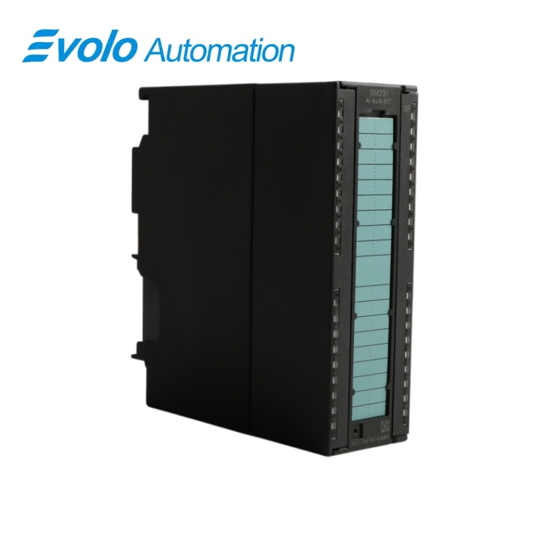
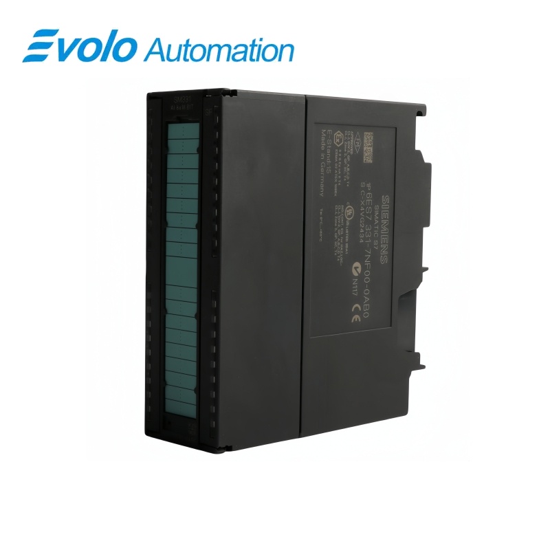
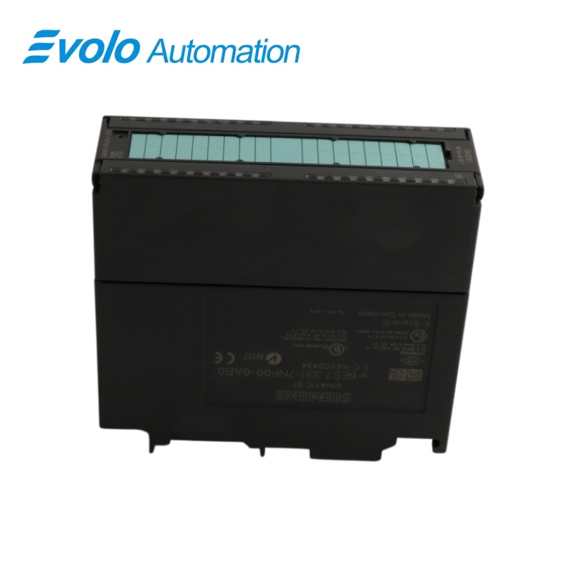
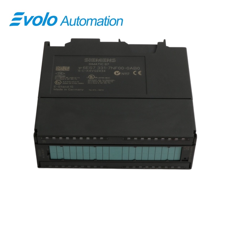
Siemens SIMATIC S7-300 6ES7331-7NF00-0AB0 SM 331 Analog Input
Manufacturer: Siemens
Condition: Brand New
Lead Time: In Stock
Origin: Germany
Warranty: 12 Months
Email: [email protected]
whatsApp: +86-18150117685
- Overview
- Product Overview
- Key Functions
- Official Specifications
- Frequently Asked Questions
- Compatibility & Ordering Notes
- Hot Selling Models
- Recommended Products
Overview
Siemens · SIMATIC S7-300
6ES7331-7NF00-0AB0 SM 331 16-Bit Analog Input Module
Siemens 6ES7331-7NF00-0AB0 is the SIMATIC S7-300 SM 331 isolated analog input module with eight channels for ±5 V, ±10 V, 1 to 5 V, ±20 mA and 0/4 to 20 mA process signals.
At a Glance
| Brand | Siemens |
|---|---|
| Model | 6ES7331-7NF00-0AB0 |
| Product Type | Isolated eight-channel analog input module |
| Core Function | Acquires precision voltage and current signals with 16-bit conversion |
| Application or Compatible Series | SIMATIC S7-300 and ET 200M systems |
Range Assignment
Match every channel group to the installed voltage or current signal range.
Common Potential
Keep the measured circuits within the documented common-mode and grounding arrangement.
Connector Transfer
Copy the forty-pole terminal allocation, polarity and shielding before replacement.
Product Overview
Siemens 6ES7331-7NF00-0AB0 is the SIMATIC S7-300 SM 331 isolated analog input module with eight channels for ±5 V, ±10 V, 1 to 5 V, ±20 mA and 0/4 to 20 mA process signals.
Sixteen-bit conversion provides detailed acquisition of industrial voltage and current signals. Bipolar and unipolar voltage and current ranges support common process transmitters. The analog input circuitry is isolated from the S7-300 backplane bus.
Key Functions
Precision Conversion
Sixteen-bit conversion provides detailed acquisition of industrial voltage and current signals.
Mixed Electrical Ranges
Bipolar and unipolar voltage and current ranges support common process transmitters.
Galvanic Separation
The analog input circuitry is isolated from the S7-300 backplane bus.
Official Specifications
| Backplane Current at 5 V DC | 130 mA maximum |
|---|---|
| Typical Power Loss | 0.6 W |
| Number of Analog Inputs | 8 |
| Maximum Continuous Voltage Input | 50 V |
| Maximum Current Input | 32 mA |
| Supported Voltage Ranges | 1 to 5 V, ±5 V and ±10 V |
| Voltage-Input Resistance | 2 MΩ |
| Supported Current Ranges | 0 to 20 mA, 4 to 20 mA and ±20 mA |
| Current-Input Resistance | 250 Ω |
| Conversion Time | 55 ms |
| Maximum Common-Mode Voltage | 50 V |
| Channel Grouping | 2 channels per group |
| Isolation from Backplane Bus | 500 V DC test voltage |
| Required Front Connector | 40-pin |
| Group-Fault Indication | Red SF LED |
| Dimensions | 40 x 125 x 117 mm |
| Approximate Weight | 272 g |
Frequently Asked Questions
Which signal ranges can I assign to 6ES7331-7NF00-0AB0?
Configure each channel group for one of the supported bipolar voltage, unipolar voltage or current ranges.
Can 6ES7331-7NF00-0AB0 measure a Pt100 sensor directly?
No, the module is intended for voltage and current inputs rather than resistance-temperature sensors.
How should I ground transmitters connected to 6ES7331-7NF00-0AB0?
Use the documented single common-potential arrangement and keep the common-mode voltage within fifty volts.
What should I copy before replacing 6ES7331-7NF00-0AB0?
Copy the channel-group ranges, forty-pin connector wiring, polarity, grounding and shielding.
How long does one conversion take on 6ES7331-7NF00-0AB0?
The specified conversion time is fifty-five milliseconds.
What input overload must be avoided on 6ES7331-7NF00-0AB0?
Keep voltage inputs at or below fifty volts and current inputs below thirty-two milliamperes.
Why might 6ES7331-7NF00-0AB0 show a red SF indication?
A configured diagnostic condition or channel fault can activate the group-fault LED.
Compatibility & Ordering Notes
Compatibility Checklist
- Confirm the rack is configured for the exact eight-channel 16-bit SM 331 module.
- Use voltage or current transmitters within the supported ranges and common-mode limit.
- Retain the two-channel grouping, connector assignment, grounding and diagnostic parameters.