EN




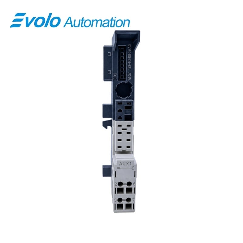
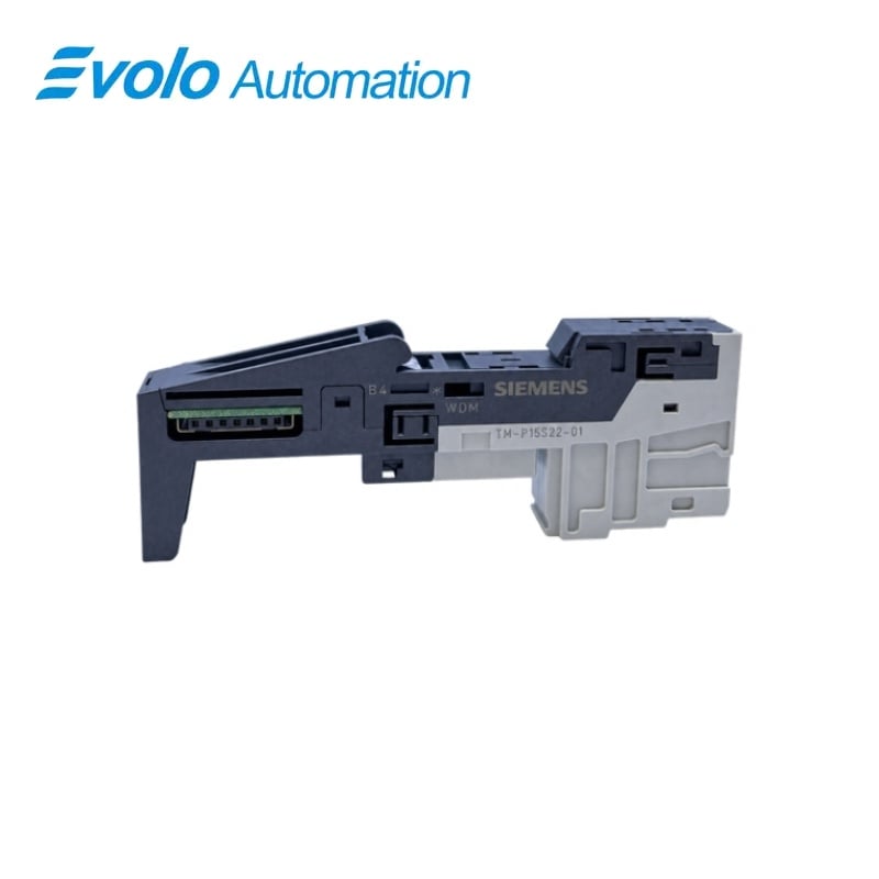
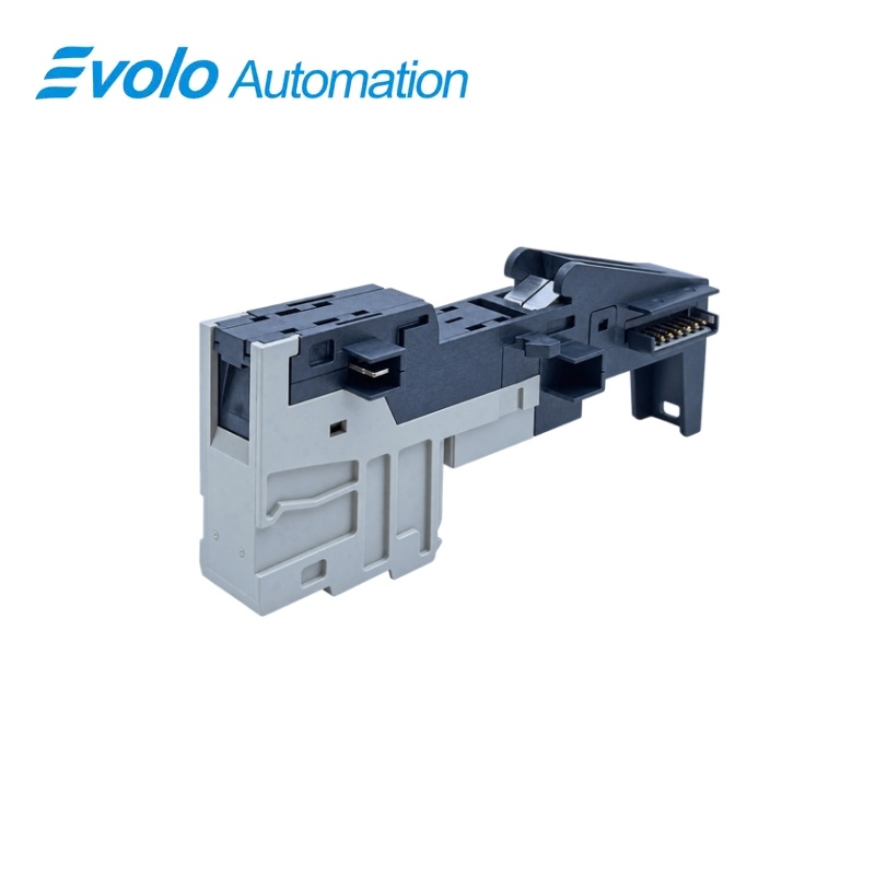
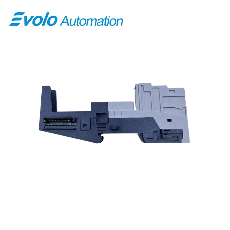
Siemens 6ES7193-4CE000-0AA0 SIMATIC ET 200S TM-P15S22-01 Screw Terminal Module
Manufacturer: Siemens
Condition: Brand New
Lead Time: In Stock
Origin: Germany
Warranty: 12 Months
Email: [email protected]
whatsApp: +86-18150117685
- Overview
- Hot Selling Models
- Recommended Products
Overview
- Use this terminal base at a compatible ET 200S power-module position.
- Keep the 2 × 2 screw-terminal wiring arrangement distinct from the spring-terminal and Fast Connect versions.
- Plan the new potential group from this base to the next TM-P base.
- Retain the AUX1 connection to the potential group on the left; no local AUX1 tap is available.
- Prepare the conductors within the permitted bare-wire or ferruled cross-section range.
- Allow 15 mm of station width and use the specified 11 mm stripping length and 0.4–0.7 N·m tightening torque.
6ES7193-4CE000-0AA0 SIMATIC ET 200S TM-P15S22-01 Screw Terminal Module
A compact screw-terminal base with four connections, continuous AUX1 routing and a new potential-group infeed for ET 200S power-module positions.
At a Glance
| Brand | Siemens |
|---|---|
| Model | 6ES7193-4CE000-0AA0 |
| Product Type | Terminal base for power modules |
| Core Function | Connects the power module to the station wiring |
| Application | SIMATIC ET 200S distributed I/O stations |
Four screw connections
Two pairs of screw terminals provide the power-module connection points.
AUX1 continuity
The internal AUX1 bus continues from the group on the left without a local terminal tap.
Compact station footprint
The base measures 15 × 119.5 × 43 mm and weighs approximately 55 g.
Product Overview
6ES7193-4CE000-0AA0 provides the mechanical and electrical terminal base at an ET 200S power-module position, with screw connections for the station supply wiring.
A new potential group starts at this base and extends to the next TM-P terminal module, while the continuous AUX1 bus remains connected to the potential group on the left.
Key Functions
Introduce a new load-potential group
The power-module terminal base starts a new potential group that supplies the following station section up to the next TM-P base.
Carry AUX1 through the station
AUX1 remains continuous across the base and connected to the group on the left, with no external AUX1 terminal available at this position.
Secure the supply wiring with screw terminals
The four connection points accept prepared conductors, using an 11 mm stripping length and a tightening torque of 0.4–0.7 N·m.
Official Specifications
| Terminal Arrangement | 2 × 2 screw-terminal connections |
|---|---|
| Auxiliary Bus Topology | Continuous AUX1 bus without external AUX1 terminal access |
| Bare Conductor Cross-Section | 0.14–2.5 mm² for solid or flexible conductors |
| Ferruled Flexible Conductor Cross-Section | 0.14–1.5 mm² |
| Conductor Occupancy | One wire, or two wires up to 1.5 mm² total in a shared ferrule |
| Wire Stripping Length | 11 mm |
| Terminal Tightening Torque | 0.4–0.7 N·m |
| Maximum Wire Insulation Diameter | 3.1 mm at 1.5 mm²; 3.8 mm at 2.5 mm² |
| Wire-End Ferrule Form | DIN 46228 Form A without collar; Form E with collar for 0.25–1.5 mm²; up to 12 mm long |
| Overall Dimensions | 15 × 119.5 × 43 mm (W × H × D) |
| Approximate Weight | 55 g |
Frequently Asked Questions
Can I connect an AUX1 wire directly to 6ES7193-4CE000-0AA0?
No external AUX1 connection is provided, so the auxiliary potential is carried through the internal bus only.
Where does the potential group started at 6ES7193-4CE000-0AA0 end?
The new potential group extends to the next TM-P terminal module in the station.
Which wire sizes can I land without ferrules on 6ES7193-4CE000-0AA0?
Solid and flexible conductors without ferrules can have a cross-section of 0.14–2.5 mm².
How should I prepare and tighten the screw connections on 6ES7193-4CE000-0AA0?
Strip 11 mm of insulation, insert each conductor and tighten the screw to 0.4–0.7 N·m with a 3 mm screwdriver.
Can I use ferrules with 6ES7193-4CE000-0AA0, and what size should I select?
Flexible wires fitted with ferrules can have a cross-section of 0.14–1.5 mm².
Does 6ES7193-4CE000-0AA0 separate AUX1 from the potential group on its left?
The AUX1 bus remains electrically continuous with the group on the left.
Is 6ES7193-4CE000-0AA0 a universal base for the electronic I/O modules?
This TM-P base is intended for power modules, while the electronic I/O positions use the corresponding TM-E terminal bases.