EN




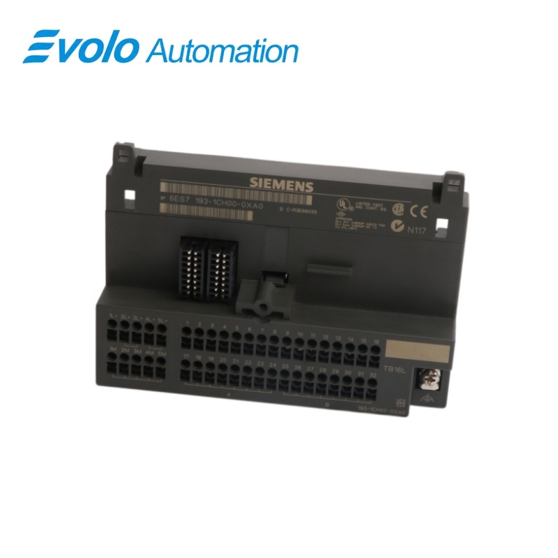
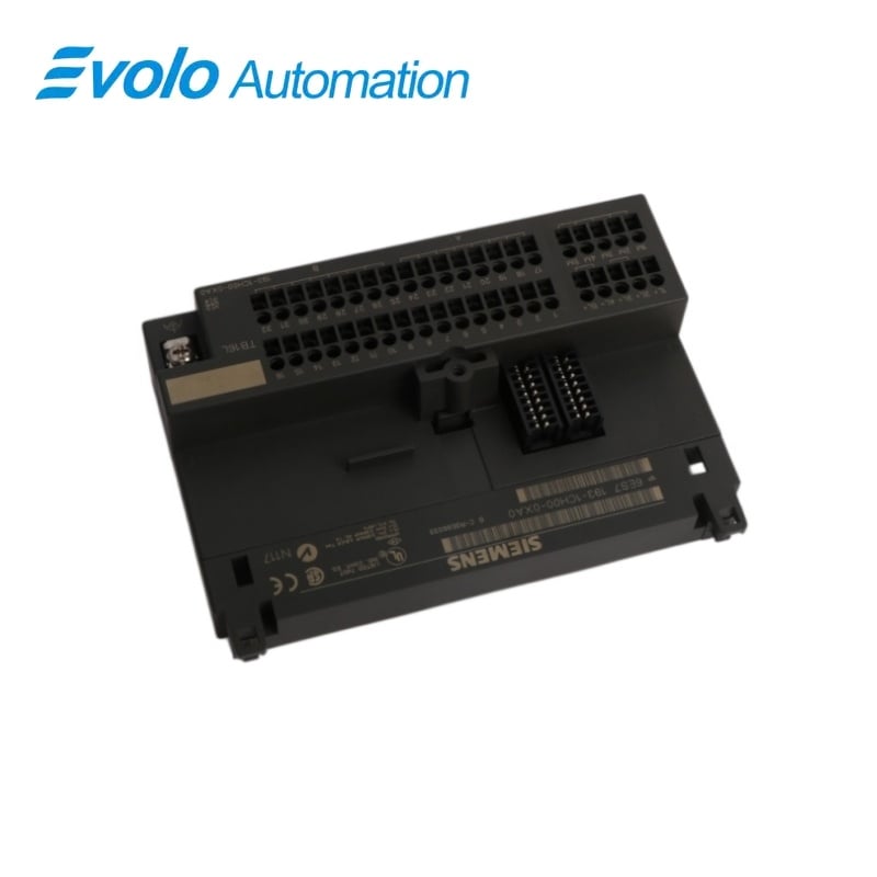
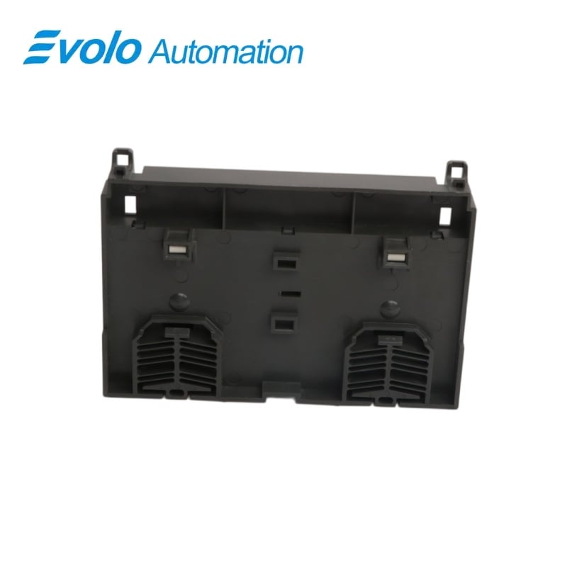
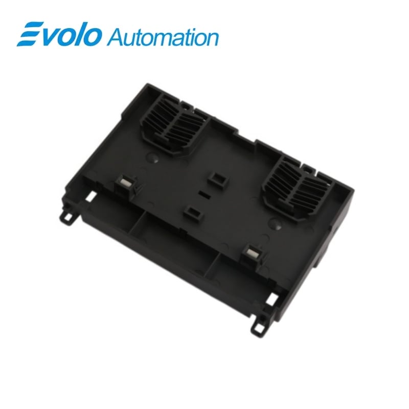
Siemens 6ES7193-1CH00-0XA0 SIMATIC ET 200L TB16L Screw-Terminal Block
Manufacturer: Siemens
Condition: Brand New
Lead Time: In Stock
Origin: Germany
Warranty: 12 Months
Email: [email protected]
whatsApp: +86-18150117685
- Overview
- Hot Selling Models
- Recommended Products
Overview
- Compatible plug-in electronics are ET 200L 16 DI DC 24 V, 6ES7131-1BH01-0XB0, and ET 200L 16 DO DC 24 V/0.5 A, 6ES7132-1BH00-0XB0.
- The spring-terminal alternative is 6ES7193-1CH10-0XA0; the ordered version here uses screw terminals.
- For additional screw-type termination tiers, use the 16-channel single-tier 6ES7193-1FH20-0XA0 or two-tier 6ES7193-1FH30-0XA0 accessory, installing it before wiring.
- Reserve 145 mm of rail width, at least 35 mm above the block and 20 mm below when using the specified supplementary terminal.
- Keep the input sensor-supply and output chassis-ground assignments distinct on terminals 17 through 32.
- The ET 200L installation uses a grounded supply; preserve the common reference and the separate channel/electronics supply arrangement.
- Isolate the supply before removing the electronics or terminal block, and tighten unwired terminal screws as well as wired ones.
6ES7193-1CH00-0XA0 SIMATIC ET 200L TB16L Screw-Terminal Block
A 16-channel screw-terminal base with stationary field wiring, separate supply connections for channel groups and electronics, and a 145 mm wide DIN-rail footprint.
At a Glance
| Brand | Siemens |
|---|---|
| Model | 6ES7193-1CH00-0XA0 |
| Product Type | TB16L terminal block |
| Core Function | Retains field wiring beneath removable electronics |
| Application | SIMATIC ET 200L distributed I/O stations |
Wiring stays on the base
The plug-in electronics can be removed while the terminal block retains its field wiring.
Defined supply groups
1L+ supplies group A, 2L+/3L+ supplies group B, and 4L+/5L+ supplies the electronics.
Front-access termination
Signal, supply and reference terminals are marked and accessible from the front.
Product Overview
6ES7193-1CH00-0XA0 forms the stationary wiring base for a SIMATIC ET 200L station with a compatible 16-channel digital input or output electronics block.
The screw terminals separate the field connections from the removable electronics, while the terminal layout provides two signal groups, auxiliary sensor-supply or output-reference connections, and dedicated electronics-supply terminals; the PROFIBUS connection is located on the electronics block.
Key Functions
Keep field wiring separate from electronics
The base carries the stationary wiring, allowing the electronics block to be detached after the supply is isolated and its bus connector and fixing screw are released.
Distribute channel and electronics supplies
Group A connects at 1L+, group B at the internally linked 2L+ and 3L+ terminals, and the electronics at the internally linked 4L+ and 5L+ terminals.
Terminate signals from the front
Terminals 1 through 16 carry the two signal groups, while terminals 17 through 32 provide sensor supply with input electronics or chassis-ground connections with output electronics.
Official Specifications
| Terminal-block dimensions (W × H × D) | 145 × 100 × 40.5 mm |
|---|---|
| Assembled projection from top edge of DIN rail | 82 mm with electronics block and bus connector 6ES7972-0CA30-0XA0 |
| Approximate terminal-block weight | 230 g |
| Signal-conductor cross-section | 0.14–1.5 mm² for solid conductors and for flexible conductors with or without wire-end ferrules |
| Conductors per terminal | One conductor, or two conductors totaling at most 1.5 mm² in one common ferrule |
| Maximum conductor-insulation diameter | 3.1 mm; 3.8 mm for a 2.5 mm² conductor |
| Insulation stripping length | 7–11 mm; 11 mm in the screw-terminal wiring procedure |
| Terminal-screw tightening torque | 0.4–0.7 N·m permissible range; 0.5 N·m specified for wiring |
| Ground-connection termination | Cable lug for an M4 screw, conductor cross-section up to 6 mm² |
| Screwdriver blade width | 3.5 mm, cylindrical design |
| Mounting rail | EN 50022, 35 × 7.5 mm or 35 × 15 mm |
| Signal-terminal assignment | 1–8: signals .0–.7 of I0 or Q0; 9–16: signals .0–.7 of I1 or Q1 |
| Auxiliary field-terminal assignment | 17–24 and 25–32: sensor supply for I0/I1 with input electronics, or internally jumpered chassis ground for Q0/Q1 with output electronics |
| Channel-group supply terminals | 1L+: group A; 2L+ and 3L+: group B, internally jumpered |
| Electronics-supply terminals | 4L+ and 5L+, internally jumpered |
| Common-reference terminals | 1M through 5M are internally jumpered for both channel groups and the electronics |
Frequently Asked Questions
Where should the PROFIBUS cable be connected when installing 6ES7193-1CH00-0XA0?
Connect the PROFIBUS cable to the bus connection on the electronics block rather than to the field-wiring base.
What changes on terminals 17–32 when 6ES7193-1CH00-0XA0 is used with output electronics?
These terminals provide internally jumpered chassis-ground connections for the output groups instead of the sensor supply used with input electronics.
Can two field wires share one screw terminal on 6ES7193-1CH00-0XA0?
Two conductors may share a connection when their combined cross-section does not exceed 1.5 mm² and both are crimped in one common wire-end ferrule.
How tightly should unused terminal screws on 6ES7193-1CH00-0XA0 be secured?
Tighten unwired terminal screws as well as wired screws to the 0.5 N·m torque specified for the screw-terminal wiring procedure.
How much cabinet depth should be reserved for 6ES7193-1CH00-0XA0 with its bus connector fitted?
Allow at least 82 mm from the rail reference for the assembly with electronics and the specified 6ES7972-0CA30-0XA0 bus connector on a 35 × 7.5 mm rail.
Must field wiring be disconnected to detach the electronics block from 6ES7193-1CH00-0XA0?
The field wiring can remain on the terminal base while the electronics block is removed after switching off the supply, removing the bus connector and loosening the fixing screw.
Which cable lug fits the ground connection on 6ES7193-1CH00-0XA0?
The ground connection accepts a cable lug for an M4 screw with a conductor cross-section up to 6 mm².