EN




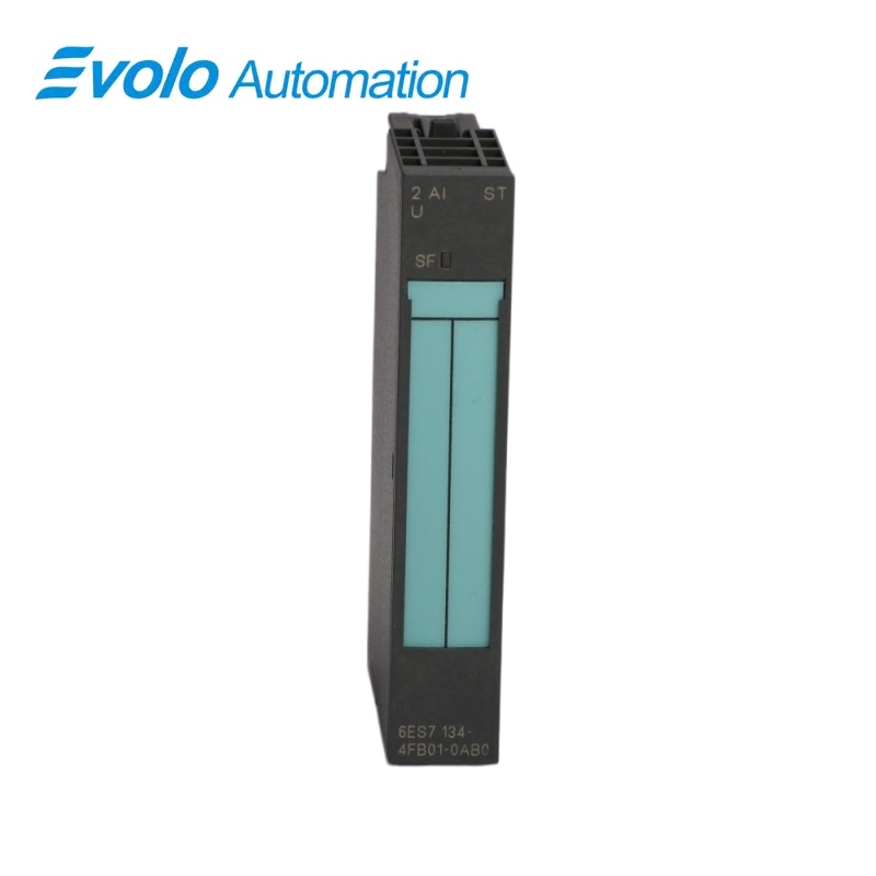
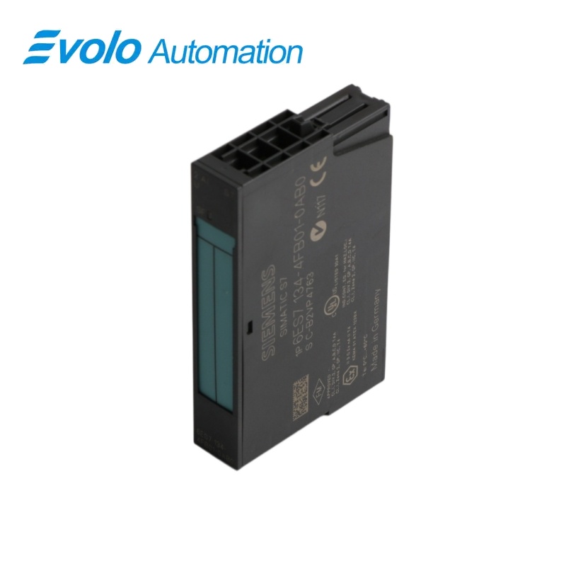
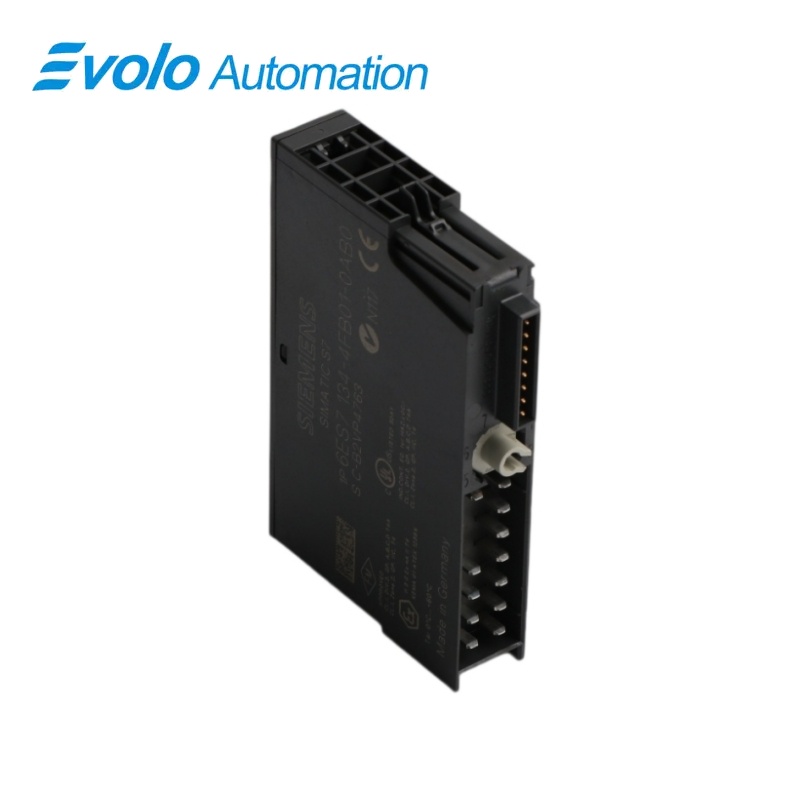
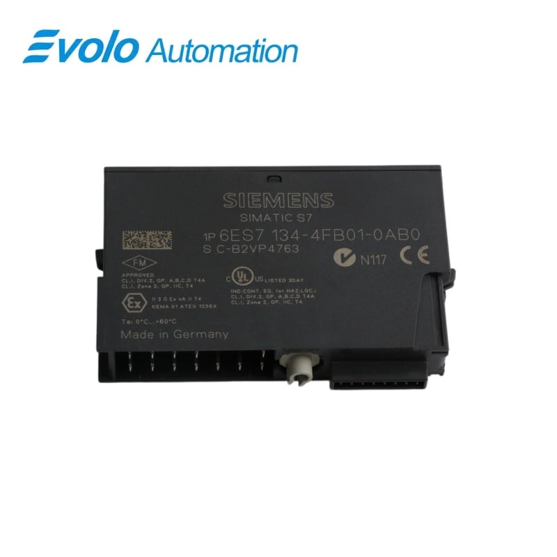
Siemens 6ES7134-4FB01-0AB0 SIMATIC ET 200S 2AI Standard Voltage Input Module
Manufacturer: Siemens
Condition: Brand New
Lead Time: In Stock
Origin: Germany
Warranty: 12 Months
Email: [email protected]
whatsApp: +86-18150117685
- Overview
- Hot Selling Models
- Recommended Products
Overview
- Configure the selected voltage range for each active channel.
- Use the 1–5 V range when the application requires wire-break detection.
- Choose the integration time and smoothing factor to suit the response requirement.
- Use shielded signal cables within 200 m and the matching ET 200S terminal base.
6ES7134-4FB01-0AB0 SIMATIC ET 200S 2AI Standard Voltage Input Module
Two-channel Standard U module for ±10 V, ±5 V and 1–5 V signals, with selectable mains rejection and four-stage digital smoothing.
At a Glance
| Brand | Siemens |
|---|---|
| Model | 6ES7134-4FB01-0AB0 |
| Product Type | Analog voltage input module |
| Core Function | Acquisition of bipolar and live-zero voltage signals |
| Application | ET 200S analog measurement stations |
Bipolar and live-zero ranges
The two inputs support ±10 V, ±5 V and 1–5 V voltage signals.
Integrating conversion
Selectable integration and digital smoothing reduce line-frequency and process-signal interference.
Range-dependent diagnostics
The live-zero range supports wire-break detection, with group-fault and range-limit diagnostics for the module.
Product Overview
6ES7134-4FB01-0AB0 acquires two analog voltage signals in a fifteen-millimeter ET 200S module.
The integrating converter supports configurable 50/60 Hz interference rejection, selectable smoothing and diagnostics for wire break in the 1–5 V range, plus overflow and underflow detection.
Key Functions
Bipolar and live-zero ranges
The two inputs support ±10 V, ±5 V and 1–5 V voltage signals.
Integrating conversion
Selectable integration and digital smoothing reduce line-frequency and process-signal interference.
Range-dependent diagnostics
The live-zero range supports wire-break detection, with group-fault and range-limit diagnostics for the module.
Official Specifications
| Analog input count | 2 |
|---|---|
| Input ranges | ±10 V; ±5 V; 1–5 V |
| Maximum resolution including sign | 14 bits |
| Nominal supply | 24 V DC from the power module; reverse-polarity protection |
| Maximum L+ current without load | 30 mA |
| Maximum 3.3 V backplane current | 10 mA |
| Typical power loss | 0.6 W |
| Input address space | 4 bytes |
| Continuous overvoltage limit | 35 V |
| Transient input limit | 75 V for up to 1 ms, mark-to-space ratio 1:20 |
| Maximum shielded cable | 200 m |
| Measuring principle | Integrating conversion |
| Integration settings | 16.7 or 20 ms |
| Per-channel conversion time | 55 or 65 ms |
| Digital smoothing factors | 1, 4, 32 or 64 times the cycle time |
| Operational voltage error | ±0.6% of input range |
| Basic voltage error at 25°C | ±0.4% of input range |
| Wire-break detection | Available in the 1–5 V range |
| Isolation | Inputs isolated from backplane and L+; no channel isolation; 500 V DC test |
| Dimensions and weight | 15 × 81 × 52 mm (W × H × D); approximately 40 g |
Frequently Asked Questions
Will 6ES7134-4FB01-0AB0 accept a ±5 V position signal?
The selectable voltage ranges include ±5 V as well as ±10 V and 1–5 V.
Which range enables wire-break monitoring on 6ES7134-4FB01-0AB0?
Wire-break monitoring is available only in the 1–5 V measuring range.
How much input address space should I assign to 6ES7134-4FB01-0AB0?
The module occupies four input bytes.
How can I smooth a noisy process value on 6ES7134-4FB01-0AB0?
Select one of the digital filter stages using one, four, thirty-two or sixty-four times the cycle time.
Can I use 6ES7134-4FB01-0AB0 for isochronous acquisition?
The Standard module does not support isochronous mode.
How much continuous overvoltage can an input of 6ES7134-4FB01-0AB0 withstand?
The specified continuous input-voltage destruction limit is 35 V.
Are the two sensor channels of 6ES7134-4FB01-0AB0 galvanically isolated from one another?
The inputs share their channel reference while remaining isolated from the backplane and load supply.