EN




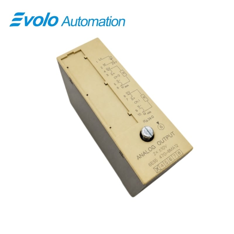
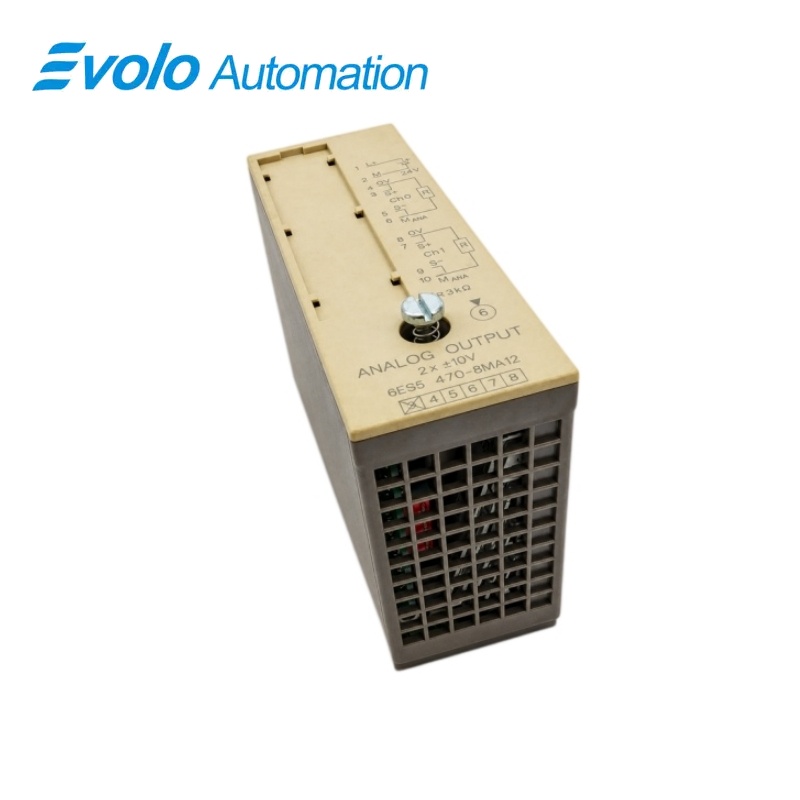
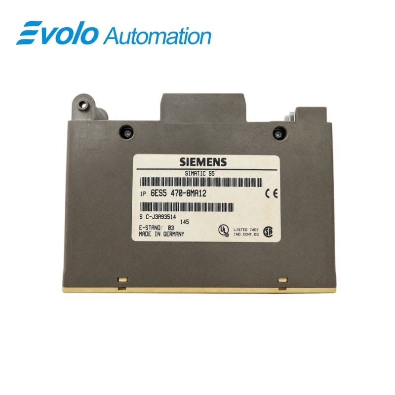
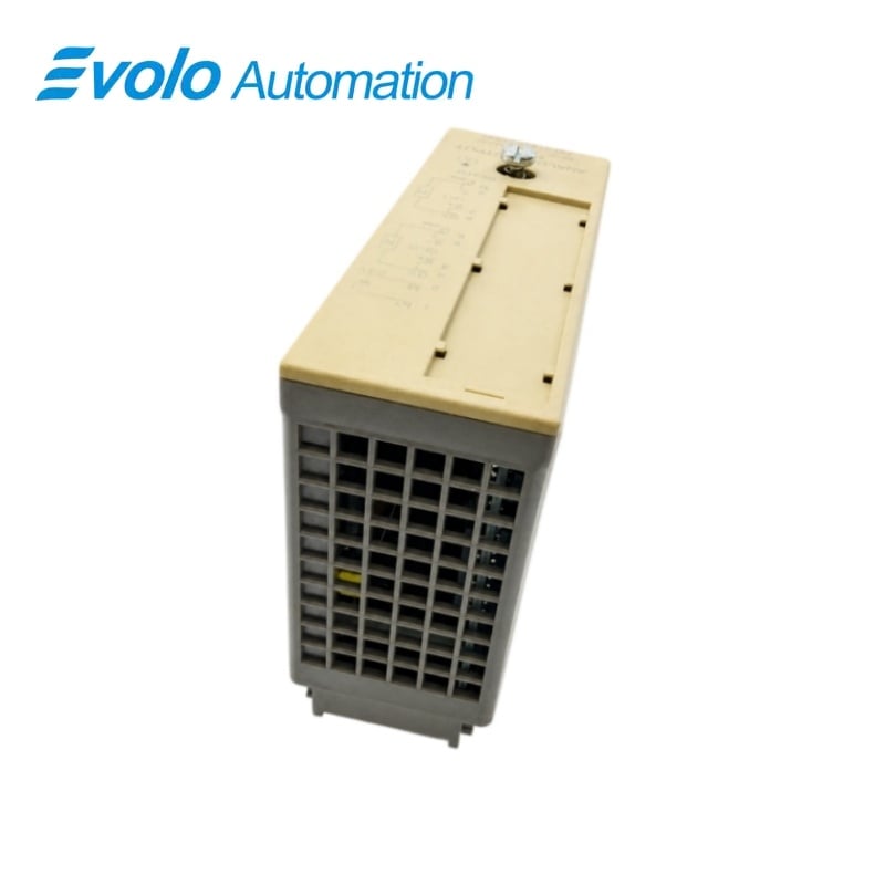
Siemens 6ES5470-8FA12 S5 Analog Voltage Output Module
Manufacturer: Siemens
Condition: Brand New
Lead Time: In Stock
Origin: Germany
Warranty: 12 Months
Email: [email protected]
whatsApp: +86-18150117685
- Overview
- Hot Selling Models
- Recommended Products
Overview
- Use a receiving load of at least 3.3 kΩ for the ±10 V output.
- Connect the 24 V DC peripheral supply to terminals 1 and 2 within the 20–30 V range.
- Connect sensing lines at the load for four-wire compensation, or bridge S+ to QV and S− to MANA when sensing leads are omitted.
- Leave unused channels open and keep shielded load cables within 200 m.
6ES5470-8FA12 S5 Analog Voltage Output Module
Two isolated ±10 V output channels with two- or four-wire load connection and short-circuit protection.
At a Glance
| Brand | Siemens |
|---|---|
| Model | 6ES5470-8FA12 |
| Product Type | Isolated analog output assembly |
| Core Function | Conversion of CPU values to analog voltages |
| Application | S5-100U voltage-output circuits |
Bipolar analog output
Generate positive or negative voltage commands over the ±10 V nominal range.
Remote load sensing
Four-wire sensing can compensate for wiring voltage drops of up to 3 V per line.
Isolated output circuits
The two output circuits are isolated from one another and from the grounding point.
Product Overview
6ES5470-8FA12 converts the S5 CPU output values into two bipolar analog voltage signals.
The output circuits are galvanically isolated from the grounding point and from one another, while four-wire sensing can compensate for voltage drops in the load wiring.
Key Functions
Bipolar analog output
Generate positive or negative voltage commands over the ±10 V nominal range.
Remote load sensing
Four-wire sensing can compensate for wiring voltage drops of up to 3 V per line.
Isolated output circuits
The two output circuits are isolated from one another and from the grounding point.
Official Specifications
| Output Channels | 2 |
|---|---|
| Nominal Output Range | −10 to +10 V |
| Minimum Load Resistance | 3.3 kΩ |
| Load Connection | Two-wire or four-wire |
| Digital Output Resolution | 11 bits plus sign; 1,024 units represent the rated value |
| Numeric Representation | Left-justified two’s complement |
| Maximum Full-Scale Conversion Time | 0.15 ms |
| Permissible Overload | 25% |
| Short-Circuit Current | ±30 mA |
| Permissible Potential Difference | 75 V DC or 60 V AC to ground and between outputs |
| Basic Error Limit | ±0.3% |
| Operational Error Limit at 0–60 °C | ±0.6% |
| Linearity Error | ±0.2% |
| Polarity Reversal Error | ±0.1% |
| Temperature Error | ±0.01%/K |
| Maximum Shielded Cable | 200 m |
| Peripheral Supply | 24 V DC nominal; 20–30 V including ripple; maximum ripple 3.6 V peak-to-peak |
| Typical Supply Consumption | 120 mA from the CPU’s 9 V supply; 100 mA from L+ |
| Typical Power Loss | 3.1 W |
| Approximate Weight | 220 g |
Frequently Asked Questions
Can 6ES5470-8FA12 generate negative voltage commands?
The two output channels cover the nominal −10 to +10 V range.
Can I connect a 1 kΩ receiving input to 6ES5470-8FA12?
The minimum load resistance is 3.3 kΩ, so a 1 kΩ input is below the permitted load resistance.
How can I compensate for voltage drop in the load wiring of 6ES5470-8FA12?
Connect the sensing lines directly at the load in a four-wire circuit to compensate for up to 3 V of drop per line.
How should unused output channels on 6ES5470-8FA12 be wired?
Unused outputs must be left open-circuited.
How should I format the output word for 6ES5470-8FA12?
The output signal uses left-justified two’s complement with eleven value bits plus sign.
Are the outputs on 6ES5470-8FA12 isolated from one another?
The output circuits are galvanically isolated from one another and from the grounding point.
Where should I connect the peripheral supply for 6ES5470-8FA12?
Connect the 24 V DC peripheral supply to terminals 1 and 2.