EN
EN




- Overview
- Quick Detail
- Description
- Applications
- Specifications
- Features
- Fault Detection Mechanisms
- Frequently Asked Questions
- Recommended Products
Overview
Place of Origin: |
USA |
Brand Name: |
GE |
Model Number: |
IS200TRLYH1BGF |
Packaging Details: |
Original new Factory Sealed |
Delivery Time: |
5-7 days |
Payment Terms: |
T/T |
Supply Ability: |
In stock |
Quick Detail
|
Product Type |
Relay Output Board |
|
Temperature Rating |
0 to 60 °C |
|
Operating Temperature |
-30 to +65 °C |
|
Dimensions |
33x17.6x6cm |
|
Weight |
1.14 kg |
|
Relay Configuration |
12 plug-in magnetic relays |
|
Relay Circuits 1–6 |
Jumper-configurable outputs |
|
Output Type |
Dry Form-C contact or external solenoid drive |
|
Relay Outputs 7–11 |
Unpowered isolated Form-C contacts |
|
Relay Output 12 |
Isolated Form-C contact for specialized applications |
|
Power Supply Options |
125 VDC or 115/230 VAC |
|
Optional Power Supply |
24 VDC |
Description
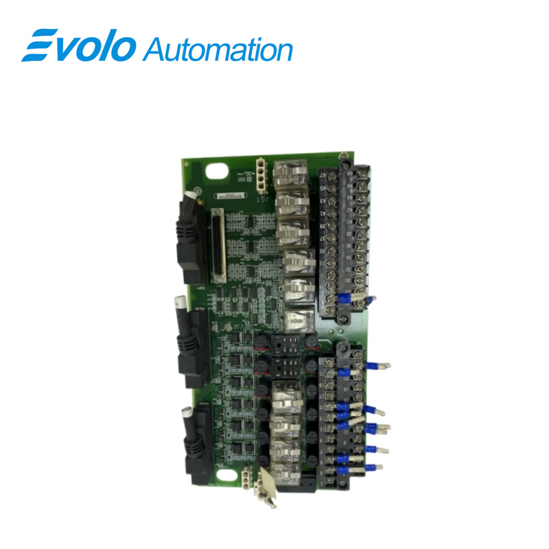
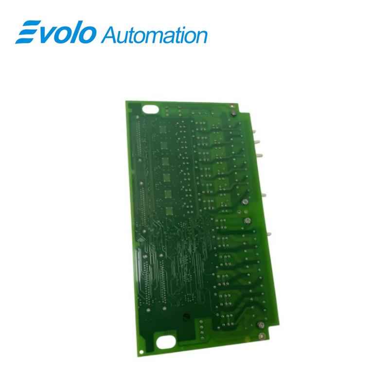
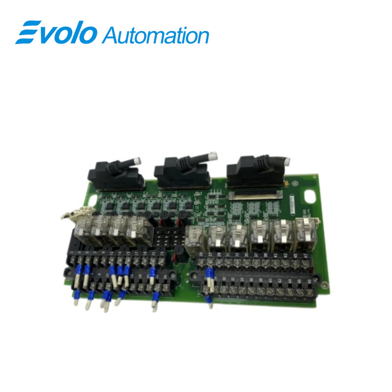
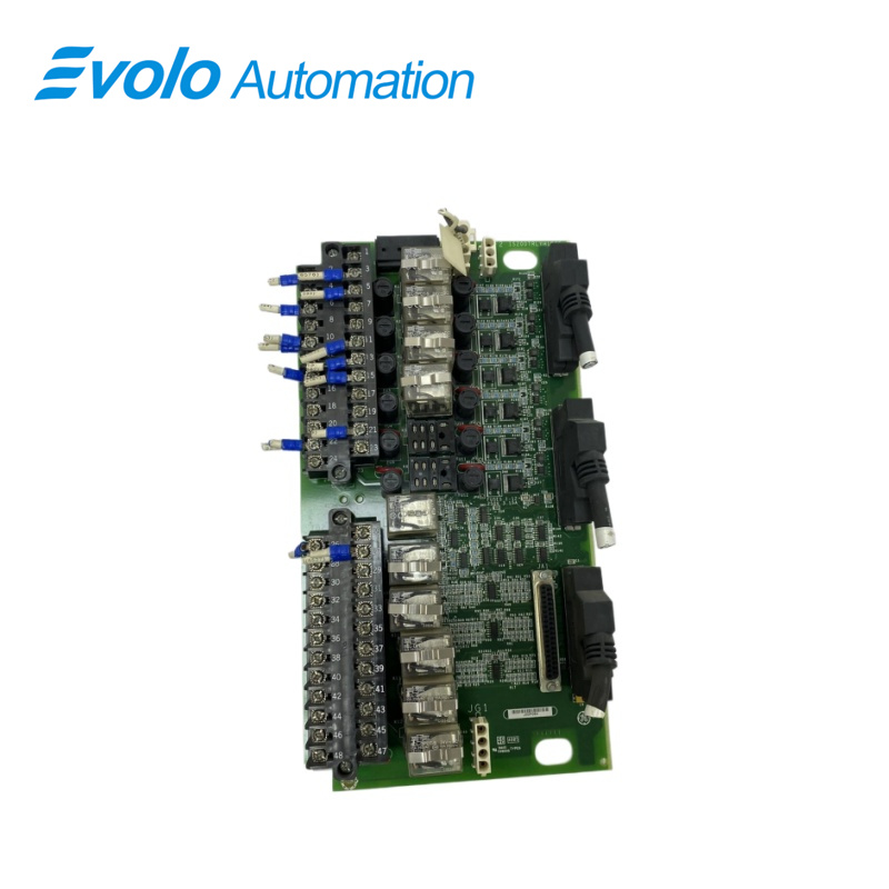
IS200TRLYH1BGF is a relay output board developed by GE. It is a part of Mark VI control system. In Mark VI systems,TRLY is under the control of either the VCCC, VCRC, or VGEN board, catering to both simplex and TMR configurations. Cables featuring molded plugs establish the connection between the terminal board and the VME rack, where the I/O boards reside. For simplex setups, Connector JA1 is utilized, while TMR systems employ connectors JR1, JS1, and JT1. The GE-IS200TRLYH1BGF is part of the GE Mark VI series control system and also belongs to the IS200 series. This series of products also includes other models such as IS200TRLYH1BGF2 (32 analog input points) and IS200TRLYH1BGF3 (32 analog output points).
Applications
Power plant monitoring: A monitoring system used in power plants.
Manufacturing of intelligent flat tempering furnaces: The manufacturing process used for intelligent flat tempering furnaces.
PLC conveyor control: Used for PLC conveyor control.
Caustic control: Used for caustic control.
Fire water supply control: Used for fire water supply control.
Chemical liquid control: Used for the control of chemical liquids.
Electrical control: Used in electrical control systems
Specifications
|
Protection |
Jumper-selectable fuses |
|
Suppression |
Onboard suppression protection |
|
Integration |
Compatible with industrial control systems |
|
Installation |
Easy system integration |
|
Reliability |
Designed for demanding industrial environments |
|
Control Capability |
Flexible relay configuration |
Features
Relay Configuration: The board houses 12 plug-in magnetic relays, offering flexible configurations for different applications and requirements.
Output Options: The board's first six relay circuits are configurable via jumpers, enabling the selection between dry, Form-C contact outputs, or the driving ofexternal solenoids
Power Sources: Multiple power source options are available, including a standard 125 V DCor 115/230 V AC source, along with an optional 24 V DC source.Each
source features individual jumper-selectable fuses and onboard suppression for enhanced safety
Relay Functionality: Relays 7-11 provide unpowered isolated Form-C contacts, while output 12 offers an isolated Form-C contact designed for specialized
applications such as ignition transformers
Enhanced Control: With its configurable relay circuits and diverse power source options, the TRLYH1B terminal board provides enhanced control and flexibility in
various industrial settings
Reliable Performance: Designed for reliability and longevity, the board ensures consistent performance in demanding operational environments.
Integration and Compatibility: The board seamlessly integrates into existing control systems and is compatible with a wide range of industrial equipment and applications
Ease of Installation: Installation and setup are streamlined, allowing for easy integration into control systems without extensive modifications or adjustments.
Safety Features: The board incorporates safety features such as onboard suppression and individual jumper-selectable fuses to ensure safe and reliable operation.
Fault Detection Mechanisms
The terminal board is equipped with advanced fault detection mechanisms to ensure system integrity and reliability. These mechanisms include:
1. Loss of Relay Solenoid Excitation Current
The board detects any loss of excitation current to the relay solenoids, triggering an alarm or alert to notify operators of the issue.
This feature ensures that any disruption in solenoid excitation is promptly identified and addressed to prevent potential system malfunctions.
2.Coil Current Disagreement with Command
The TRLYH1B board continuously monitors the coil current and compares it with the commanded value.
If there is a discrepancy between the actual and commanded coil currents, the board flags this as a fault condition, indicating a potential issue with the relay
operation.
This helps maintain accuracy and consistency in relay performance, minimizing the risk of errors or inaccuracies in system operations.
3. Unplugged Cable or Loss of Communication
The board actively monitors communication with the associated I/O board, ensuring seamless data exchange and relay control.
In case of an unplugged cable or loss of communication with the I/O board, the TRLYH1B terminal board triggers relays to de-energize as a safety measure.
This proactive approach helps prevent potential hazards or disruptions caused by communication failures, ensuring continuous system functionality.
Frequently Asked Questions
What is IS200TRLYH1BGF?
It is a relay output board developed by GE under the Mark VI series.
How are control signals and feedback voltages transmitted in simplex operation?
In simplex operation, D-type connectors facilitate the transmission of control signals and monitor feedback voltages between the I/O processors and TRLY via connector JA1.
What are the specifications of the relays used on the TRLYH1B board?
The relays are driven at the frame rate and have a 3.0 A rating.They have a rated contact-to-contact voltage of 500 AC for one minute and a rated coil-to-contact voltage of 1,500 V AC for one minute.
What is the typical operation time for the relays?
The typical time to operate the relays is 10 ms.