Get a Free Quote

Our representative will contact you soon.
Email
Name
Company Name
Message
0/1000
is200edcfg1aed exciter dc feedback board-0

For GE

Home >  Products >  For GE

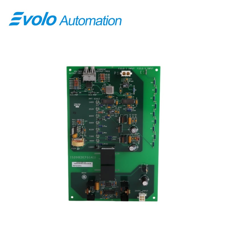
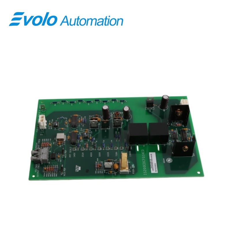
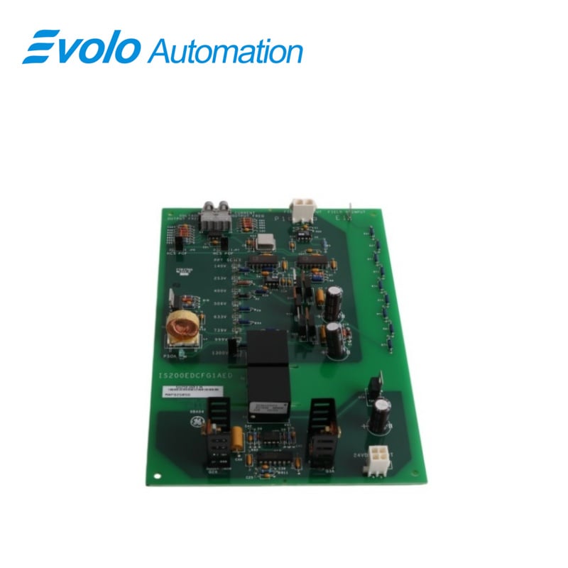
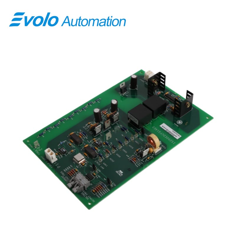
IS200EDCFG1AED Exciter DC Feedback Board

  • Overview
  • Specifications
  • Description
  • Features
  • Power Supply
  • Connectors
  • Frequently Asked Questions
  • Recommended Products
Overview

Dimensions:

22.8x15.1x3.5 cm

Weight:

0.24 kg

Product Type:

Exciter DC Feedback Board

Series:

EX2100

Technology:

Surface mount

Power Supply:

24 V DC input, regulated to +15 V DC, -15 V DC, +5 V DC

Power Indicator:

Green PSOK LED

Voltage Isolation:

Fiber-optic link to EISB

Noise Immunity:

Fiber-optic communication

Fiber Types:

Plastic (up to 10 m), Hard-Clad Silica (up to 90 m)

Signal Transmission:

Dedicated fiber-optic cables for field current and voltage

Field Voltage Input:

E1 stab-on connector

Field Current Shunt Voltage Input:

P1 connector

Power Input Connector:

J16 connector

Feedback Connections:

Fiber-optic connectors to control system

Installation Flexibility:

Supports short and long-distance fiber connections with minimum bending radius 1.5 inches

Connectors:

J16, P1, E1, fiber-optic connectors

Specifications

Dimensions:

22.8x15.1x3.5 cm

Weight:

0.24 kg

Product Type:

Exciter DC Feedback Board

Series:

EX2100

Technology:

Surface mount

Power Supply:

24 V DC input, regulated to +15 V DC, -15 V DC, +5 V DC

Power Indicator:

Green PSOK LED

Voltage Isolation:

Fiber-optic link to EISB

Noise Immunity:

Fiber-optic communication

Fiber Types:

Plastic (up to 10 m), Hard-Clad Silica (up to 90 m)

Signal Transmission:

Dedicated fiber-optic cables for field current and voltage

Field Voltage Input:

E1 stab-on connector

Field Current Shunt Voltage Input:

P1 connector

Power Input Connector:

J16 connector

Feedback Connections:

Fiber-optic connectors to control system

Installation Flexibility:

Supports short and long-distance fiber connections with minimum bending radius 1.5 inches

Connectors:

J16, P1, E1, fiber-optic connectors

Description

IS200EDCFG1AED is an Exciter Dc Feedback Board developed by GE. It is a part of the EX2100 control system.The board performs precise measurements of field current and voltage at the SCR bridge, critical parameters for excitation control systems. Utilizing a high-speed fiber-optic link, the board establishes communication with the EISB board in the control panel, ensuring rapid and reliable data transmission.

Features

Voltage Isolation: One of the standout features of the Exciter DC Feedback Board is its voltage isolation provided by the fiber-optic link between the board and the EISB (Exciter Interface and Status Board). This isolation is crucial in protecting sensitive components from high voltages, preventing electrical interference, and ensuring the overall integrity of the control system. By effectively isolating the control system from any external electrical noise or surges, the board helps maintain safe and reliable operation within the excitation control system.

Noise Immunity: The fiber-optic communication ensures superior noise immunity, making it highly effective in environments with significant electromagnetic interference (EMI). Fiber-optic cables are immune to electrical and magnetic disturbances, ensuring that the transmission of data, such as field current and voltage measurements, remains accurate even in the presence of external noise. This feature is critical for maintaining reliable system performance in harsh industrial environments where EMI is common.

Fiber Types: The board supports two types of fiber-optic cables to cater to varying installation distances and requirements

1.Plastic Type Fiber: This fiber is suitable for distances of up to 10 meters, making it ideal for shorter installation runs.

2.Hard-Clad Silica-Type Fiber: For longer distances, the hard-clad silica-type fiber is ideal, supporting distances of up to 90 meters. This ensures that thecommunication link remains reliable even over extended distances within the control system

3.Both fiber types are designed with a minimum bending radius of 1.5 inches, which helps ensure proper cable handling and installation without damaging the fibers, thereby maintaining the integrity of the signal transmission.

Signal Transmission: Each critical signal, including field current and voltage, is transmitted over a dedicated fiber-optic cable. This dedicated signal path helps to optimize signal integrity, reducing the risk of crosstalk or interference between the various signals. With this approach, the accuracy and reliability of the measurements are preserved, which is essential for proper control and regulation of the excitation system.

Installation Flexibility: The availability of two fiber types offers installation flexibility, allowing the board to be configured to meet the specific needs of the application. Whether the installation requires short-distance connections or long-distance communication, the use of either plastic or hard-clad silica fiber ensures that the setup can be customized for optimal performance. This flexibility simplifies the installation process, reduces the need for additional components, and enhances the overall systems adaptability in varying operational environments.

Power Supply

Within the board, three voltage regulators are employed to convert the incoming 24 V dc supply into three distinct voltage levels: +15 V dc,-15 V dc, and +5 V dc

The voltage regulators ensure stable and precise outputs, providing the necessary voltage levels required for the proper functioning of the EDcF board and associated components.

A green LED labeled PSOK (Power Supply OK) is integrated. This LED is illuminated when the 15 V dc output voltages from the voltage regulators are within the specified range, indicating that the power supply is functioning correctly

The psOK LED serves as a visual indicator of the operational status of the power supply, providing immediate feedback on the health of the voltage regulation system

By monitoring the illumination of the PSOK LED, operators can quickly assess the integrity of the power supply and identify any potential issues with voltage regulation. This facilitates prompt troubleshooting and maintenance actions, minimizing downtime and ensuring continuous operation of the system.

Connectors

Power Input Connector (J16): Provides stable 24 V DC power to the Exciter DC Feedback Board, ensuring continuous operation and accurate field current and voltage measurements.

Voltage Across Field Current Shunt (P1): Measures the voltage drop across the field current shunt to monitor current levels, enabling precise excitation control.

Field Voltage Input (E1): Uses a stab-on connection to securely transmit the field voltage signal for accurate generator and exciter regulation.

Feedback Connections: Transmit current and voltage readings to the control system via fiber-optic connectors, ensuring fast, noise-immune, and accurate data transfer.

Fiber-Optic Connectivity: Provides EMI immunity, high noise tolerance, and reliable long-distance data transmission for field current and voltage feedback, enhancing excitation system performance.

Frequently Asked Questions

What is IS200EDCFG1AED?

It is an Exciter DC Feedback Board developed by GE under the EX2100 series.

How is the field voltage scaled in the feedback circuit about IS200EDCFG1AED?

The field voltage feedback circuit provides seven selector settings to scale down the bridge voltage based on the specific bridge application.

What does the field voltage measurement involve about IS200EDCFG1AED?

Field voltage is measured across the negative terminal of the bridge and the positive terminal of the current shunt, followed by scaling with jumpered resistors.

How is field current measured about IS200EDCFG1AED?

Field current is measured across a DC shunt at the SCR bridge, generating a low-level signal (up to 500 mV) input to a differential amplifier.

Get a Free Quote

Our representative will contact you soon.
Email
Name
Company Name
Message
0/1000
email goToTop

Evolo Automation is not an authorized distributor unless otherwise specified, representative, or affiliate of the manufacturer of this product. All trademarks and documents are the property of their respective owners and are provided for identification and informational.