EN
EN




- Overview
- Specifications
- Description
- Applications
- Features
- Installation and Compatibility
- FAQ
- Recommended Products
Overview
Place of Origin: |
USA |
Brand Name: |
GE |
Model Number: |
IC693MDL646 |
Packaging Details: |
Original new Factory Sealed |
Delivery Time: |
5-7 days |
Payment Terms: |
T/T |
Supply Ability: |
In stock |
Specifications
|
Parameter |
Value |
|
Module Name |
IC693MDL646 Positive/Negative Logic Input Module |
|
Module Type |
Positive/Negative Logic Input Module |
|
Dimensions |
3.5 x 13 x 13.5 cm |
|
Weight |
0.28 kg |
|
Rated Voltage |
24 V DC |
|
Input Voltage Range |
0–30 V DC |
|
Inputs per Module |
16 (one group with single common) |
|
Isolation |
1500 V between field side and logic side |
|
Input Current |
7 mA typical at rated voltage |
|
On-state Voltage |
11.5–30 V DC |
|
Off-state Voltage |
0–5 V DC |
|
On-state Current |
3.2 mA minimum |
|
Off-state Current |
1.1 mA maximum |
|
On Response Time |
1 ms typical |
|
Off Response Time |
1 ms typical |
|
Power Consumption (5 V) |
80 mA (all inputs on) from 5 V bus on backplane |
|
Power Consumption (24 V) |
125 mA from isolated 24 V backplane bus or user-supplied power |
Description
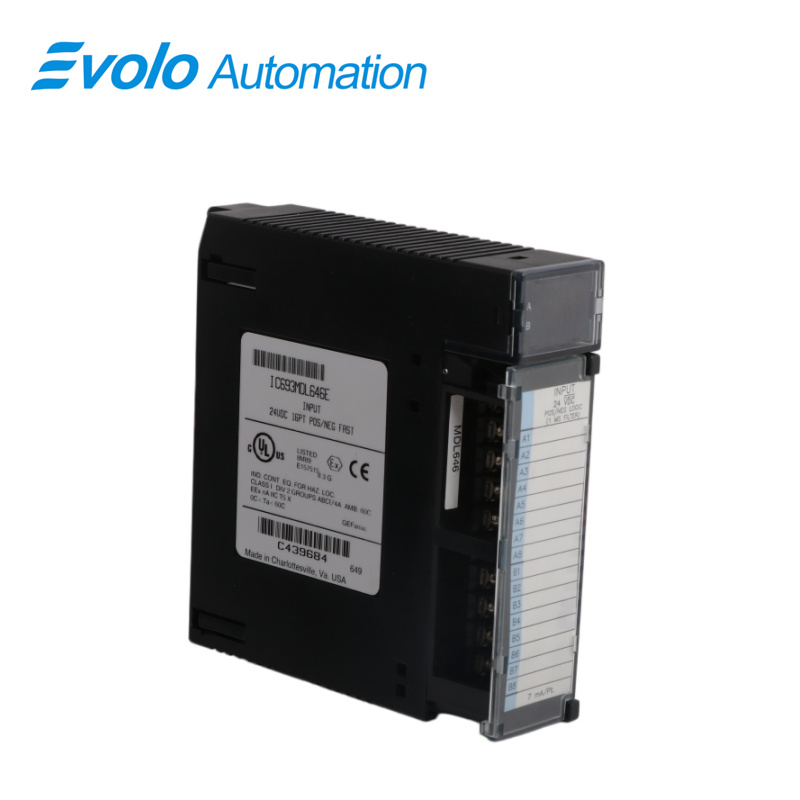
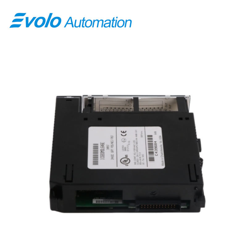
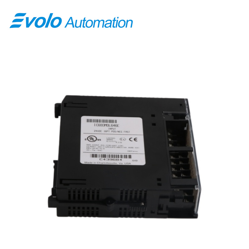
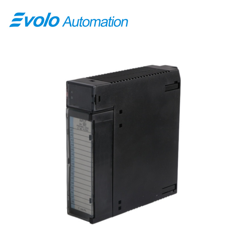
The IC693MDL646 module is a 24-volt DC positive / negative logic input module for the 90-30 series of Programmable Logic Controllers. It comes with 16 input points in one group sharing a common power input terminal. The IC693MDL646 is designed to have either positive Logic or negative logic characteristics. Input characteristics make it compatible with a wide array of user supplied input devices such as limit switches, push buttons as well as proximity switches. Power to run the field devices is normally supplied by the user or an isolated +24VDC supply on the power supply.
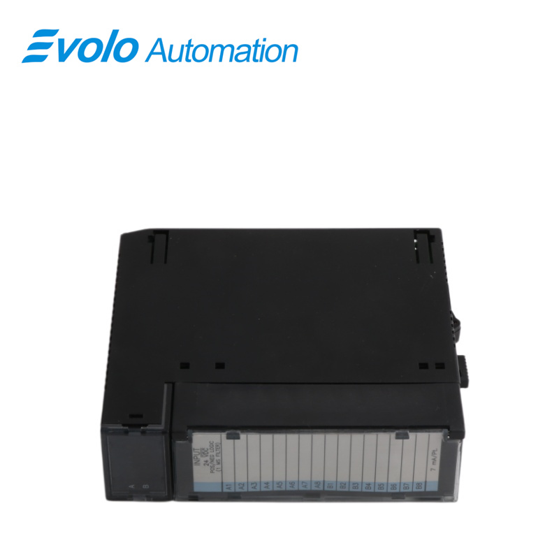
At the top of the module, one can locate LED indicators which display the ON/OFF status of each point. The LED block is partitioned into 2 horizontal rows with 8 green LEDs in each row. The top row is labelled from A1 to A8 (Point 1 to 8) and the bottom from B1 to B8 (point 9 to 16). There’s an insert that goes between the inside and outside surface of the hinged door. Towards the inside, one will find the wiring diagram, and the circuit identification is located on the outside surface. The outside left edge of the insert is color-coded blue to show a low-voltage module. This module can be installed in any I/O slot in a Series 90-30 PLC system. Other specifications include an input voltage range of 0 to 30 VDC and input current of 7 mA. The on-state voltage is between 11.5 to 30 V and on-state voltage 0- +5V DC. On-state current rating is 3.2mA minimum and off-state 1.1mA maximum.
Applications
High-speed packaging machinery: Used to monitor the position of rapidly moving packaging bags and color mark sensor feedback.
Electronics assembly plants: In SMT pick-and-place machines or dispensing machines, quickly acquire sensor trigger signals.
Precision CNC machine tools: Receive high-speed limit switches, probe signals, or encoder-divided switching signals.
Material sorting systems: Accurately capture the moment small objects pass by on high-speed conveyor belts.
Features
1 Response Time: On-state response time is typically 1 ms. Off-state response time is also typically 1 ms, ensuring fast and reliable input processing for real-time control and automation tasks.
2 Power Supply Options
User-supplied power: Users can connect their own power supply for operating the field devices
Isolated 24V DC supply: The module can draw power from the isolated +24V OUT and 0V OUT terminals on the PLC power supply, providing power to a limited number of inputs.
3 Isolation: The module provides 1500 volts of isolation between the field side and the logic side, offering protection for the PLC from potential voltage surges or electrical faults in the field devices.
4 Input Characteristics:
On-state voltage: The module recognizes inputs within the voltage range of 11.5 to 30 volts DC
Off-state voltage: The module recognizes off-state inputs within the range of 0 to +5 volts DC.
On-state current: A minimum of 3.2 mA is required for the module to register an "on" input.
Off-state current: A maximum of 1.1 mA is acceptable for the module to register an "off" input.
5 Power Consumption:
5V power consumption: The module draws 80 mA from the 5v bus on the backplane when all inputs are activated.
24V power consumption: The module consumes 125 mA from the isolated 24V backplane bus or from a user-supplied power source.
Installation and Compatibility
The module can be installed in any I/O slot within a Series 90-30 PLC system, offering flexibility in system design and expansion. It is designed to seamlessly integrate with the existing PLC infrastructure, providing reliable performance across various applications.
FAQ
Q: What is the rated voltage of IC693MDL646?
A: 24 volts DC
Q: What is the input voltage range of IC693MDL646?
A: 0 to +30 volts DC
Q: What kind of power source does this module require?
A: The IC693MDL646 can be powered by the user supply or an Isolated +24 VDC supply can power a select amount of inputs.
Q: With what are the input characteristics compatible?
A: They are compatible with pushbuttons, limit switches, and electronic proximity switches.
Q: Into what can the IC693MDL646 be installed?
A: The IC693MDL646 can be installed in any I/O slot of a 5- or 10-slot baseplate in a Series 90-30 PLC system.
Q: Why is the outside left edge of the insert color-coded blue?
A: It means that this is a low-voltage module.