EN
EN




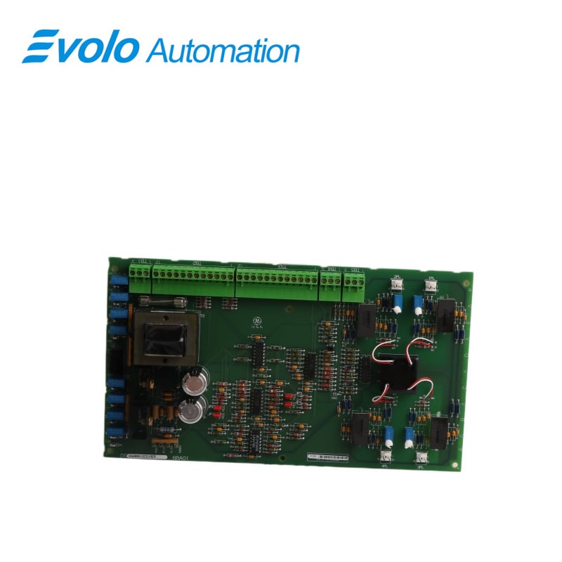
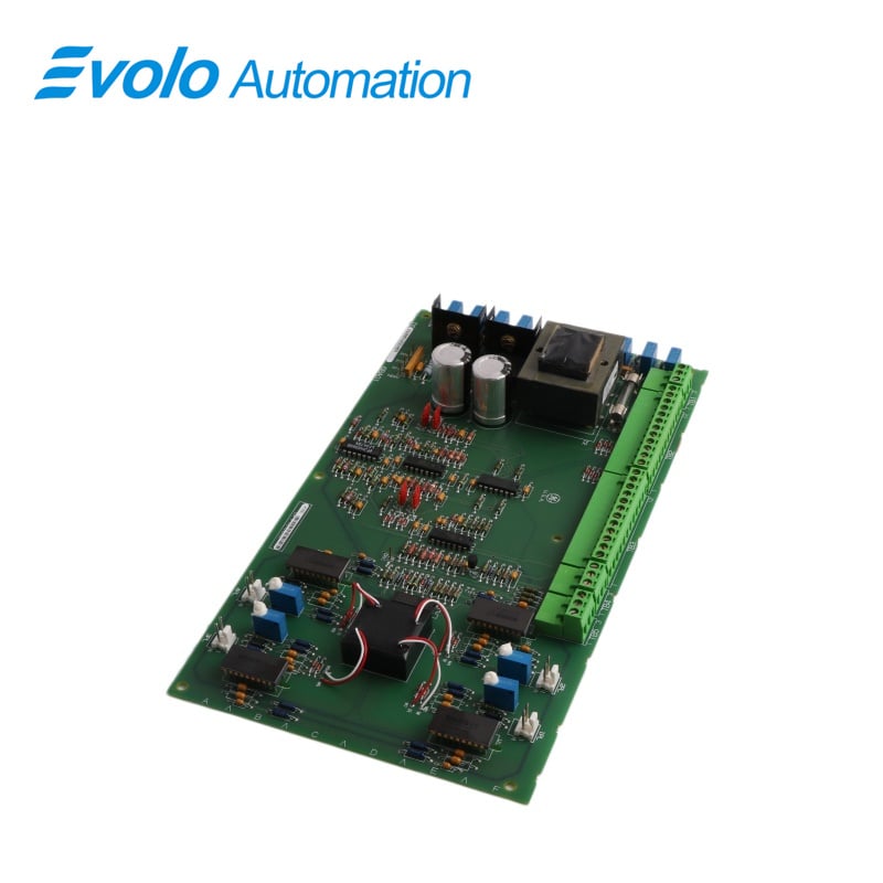
- Overview
- Specifications
- Description
- Applications
- FEATURES
- FREQUENTLY ASKED QUESTIONS
- Recommended Products
Overview
Place of Origin: |
USA |
Brand Name: |
GE |
Model Number: |
DS200SIOCG1A |
Packaging Details: |
Original new Factory Sealed |
Delivery Time: |
5-7 days |
Payment Terms: |
T/T |
Supply Ability: |
In stock |
Specifications
|
Part Number: |
DS200SIOCG1A |
|
Manufacturer: |
General Electric |
|
Series: |
Mark V |
|
Product Type: |
VME Standard I/O Board |
|
Power Supply Voltage: |
28 V dc |
|
Technology: |
Surface mount |
|
Data Transfer: |
115.2 Kbps |
|
Dimensions: |
27.8 x 15.5 x 4 cm |
|
Weight: |
0.62 kg |
|
Country of Manufacturer: |
United States (USA) |
|
Fuses: |
1 fuse |
|
Connectors: |
4 x 2-pin connectors |
Description
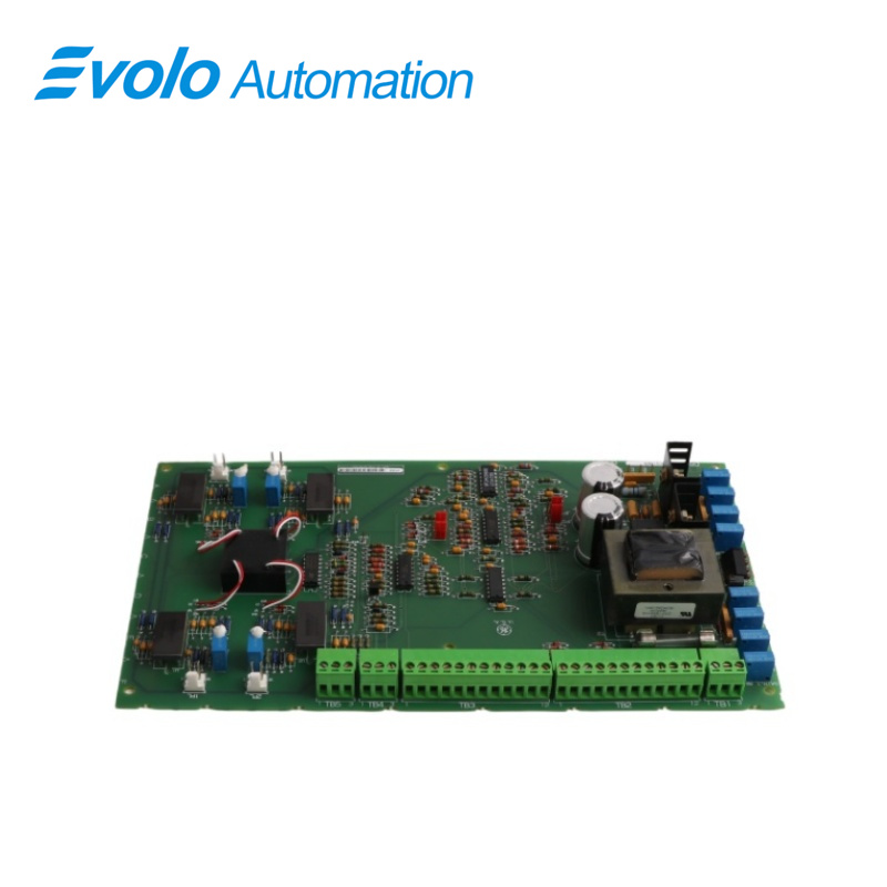
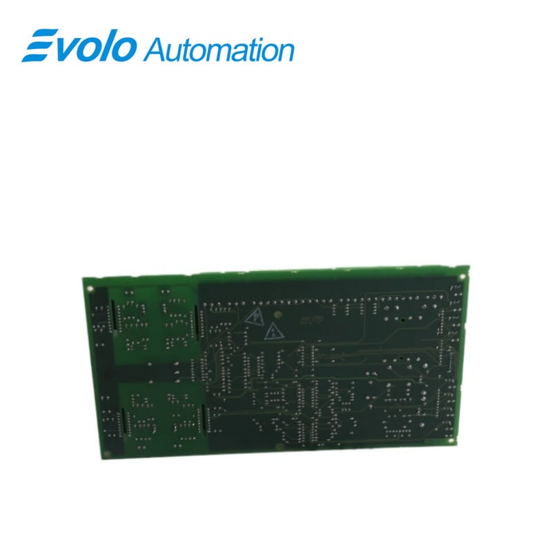
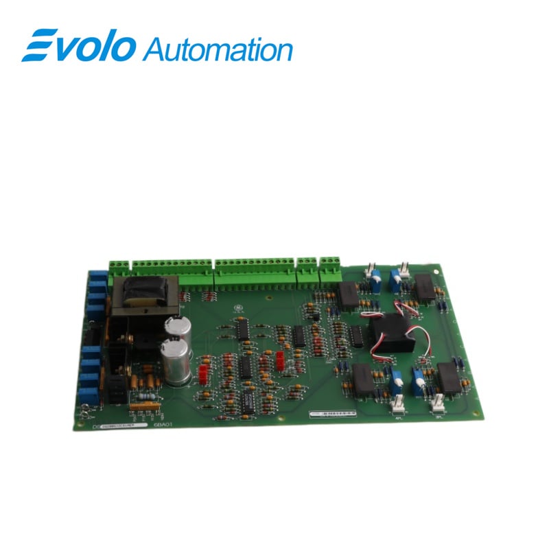
DS200SIOCG1A is a VME Standard I/O Board manufactured and designed by General Electric as part of the Mark V Series used in GE Speedtronic Control Systems. An instantaneous overcurrent board is a protection device used in electrical power systems to detect and interrupt the excessive electrical current in a circuit. It is also commonly known as an overcurrent relay or a protective relay. The device works by monitoring the current flowing through the circuit and comparing it to a pre-set threshold value. If the current exceeds this threshold value, the relay will actuate and send a signal to trip the circuit breaker, interrupting the flow of current. A VME Standard I/O (Input/Output) board is a peripheral board that conforms to the VME standard and provides various input and output functions for a VME-based system.
Applications
Power Industry: Installed in the control panels of gas turbines and steam turbines for managing generator excitation and load control.
Heavy-Duty Drive Systems: Used in large DC/AC drives to protect high-power motors from current surges during startup or sudden load changes.
Steel and Mining: Provides precise I/O feedback in control cabinets of equipment requiring extremely high transient response, such as rolling mills and hoists.
FEATURES
1.VME Standard Compatibility: The board follows the VME standard specifications.which define the mechanical dimensions.electrical characteristics.and signaling protocols for VME modules.This ensures interoperability with other VME-compliant boards and systems.
2.Input/Output Functions: The I/O board is designed to handle various input and output tasks. This can include digital and analog inputs and outputs communication interfaces (such as serial or parallel ports), and other specialized functions depending on the application requirements.
3.Bus Interface: The board connects to the VME backplane through the standard VMEbus connectors. It communicates with the system controller and other VME devices using the VMEbus protocol, allowing for data transfer and control within the VME chassis.
4.Application Specific: The specific functionalities of the I/O board depend on the intended application. For example, in a defense application, the board might include interfaces for sensors, actuators, and communication devices. In an industrial setting, it could offer control interfaces for machinery and sensors.
5.Modularity: VME Standard I/O boards are designed to be modular, allowing users to customize their VME-based systems based on their unique requirements. This modularity simplifies system upgrades and maintenance.
6.Backward Compatibility: The VME standard has been around for several decades, and many systems still use this architecture. Therefore, newer I/O boards often maintain backward compatibility with older VME systems, allowing for easy integration into existing setups.
7.Reliability and Robustness: As VME-based systems are often used in critical applications such as military and industrial control, VME Standard I/O boards are typically built to high standards of reliability and robustness, ensuring stable operation in demanding environments.
FREQUENTLY ASKED QUESTIONS
Q: How many jumpers and switch blocks are on DS200SIOCG1A?
A: The board has twenty jumpers and three switch blocks, each with six switches, for a total of 18 switches.
Q: What connectors can be synced and linked using ribbon cables on the DS200SIOCG1A?
A: Some of the connectors on the Control Board can be synced and linked using ribbon cables.
Q: What do the ribbon cables carry on the DS200SIOCG1A?
A: The ribbon cables carry several small wires that transmit signals from the board to other components in the drive, and also carry signals to the board for processing.