EN




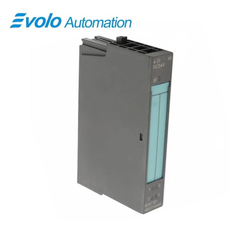
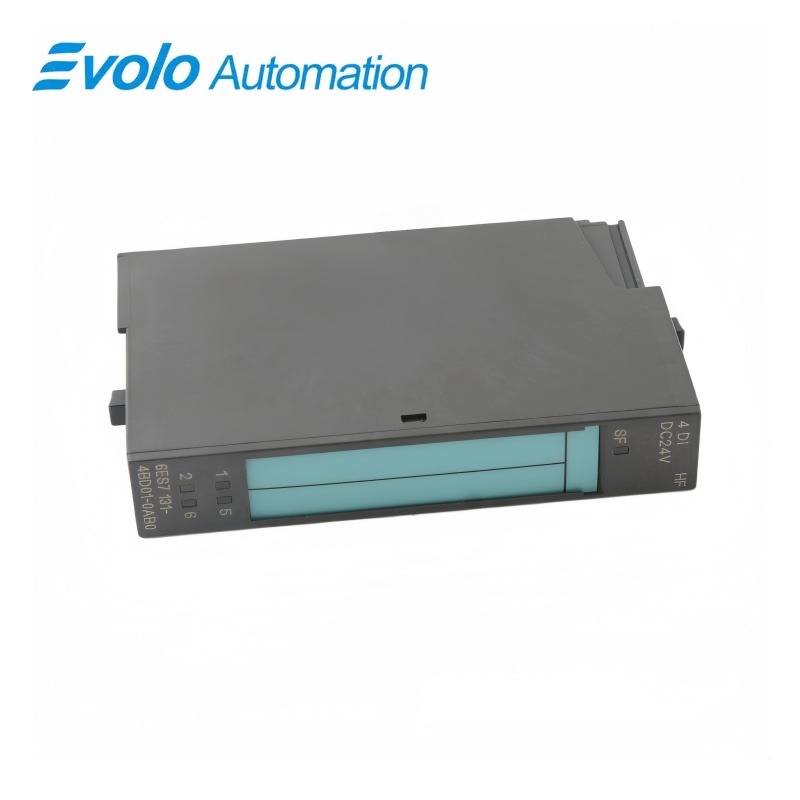
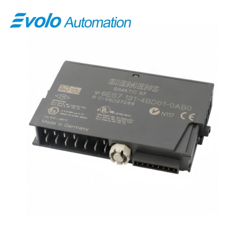
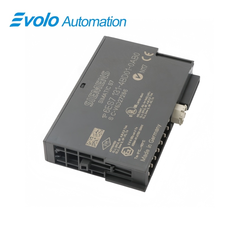
Siemens 6ES7131-4BD01-0AB0 SIMATIC ET 200S 4DI DC24V High Feature Input Module
Manufacturer: Siemens
Condition: Brand New
Lead Time: In Stock
Origin: Germany
Warranty: 12 Months
Email: [email protected]
whatsApp: +86-18150117685
- Overview
- Hot Selling Models
- Recommended Products
Overview
- Use a supported 15 mm ET 200S terminal module from the TM-E15C, TM-E15S or TM-E15N families.
- Select the terminal version for the sensor’s two-wire or three-wire connection and the required L+ or AUX1 terminals.
- Apply the selected input delay to the whole module; 3 ms is the default setting.
- For process interrupts, use IM151-1 HIGH FEATURE or IM151-7 CPU and enable both the module interrupt and the required channel’s rising-edge trigger.
- Enable sensor-supply short-circuit diagnostics when the application requires fault reporting; a reported channel-0 fault covers the entire module.
6ES7131-4BD01-0AB0 SIMATIC ET 200S 4DI DC24V High Feature Input Module
Four-channel 24 V DC input electronics with module-wide selectable filtering, a protected sensor supply and rising-edge process interrupts in compatible ET 200S stations.
At a Glance
| Brand | Siemens |
|---|---|
| Model | 6ES7131-4BD01-0AB0 |
| Product Type | High Feature digital input electronic module |
| Core Function | Acquisition of switch and proximity-sensor states |
| Application | SIMATIC ET 200S distributed I/O stations |
Filter both signal edges
One delay setting applies to the complete module and to both rising and falling transitions.
Recognize sensor faults
Sensor-supply short-circuit diagnostics identify a module-wide fault through channel 0.
Choose the terminal base
15 mm spring, screw and FastConnect terminal modules support the required sensor wiring.
Product Overview
6ES7131-4BD01-0AB0 adds four digital sensor inputs to an ET 200S station in a 15 mm-wide electronic module, accepting signals from switches and compatible proximity sensors.
High Feature functions provide configurable input filtering, sensor-supply short-circuit diagnostics and isochronous operation, while rising-edge process interrupts require a compatible interface module or station CPU.
Key Functions
Apply one filter setting across the input module
Choose a nominal delay of 0.1, 0.5, 3 or 15 ms for all four channels, with the same setting applied to both switching directions and a 3 ms default.
Separate input activity from group diagnostics
Individual green indicators show active input channels, while the red SF indicator reports group faults or a missing parameter assignment.
Trigger the program on selected rising edges
Each input channel can trigger a rising-edge process interrupt when the function is enabled with an IM151-1 HIGH FEATURE interface or IM151-7 CPU.
Official Specifications
| Digital Input Channels | 4 |
|---|---|
| Rated Supply and Input Voltage | 24 V DC; supply from the power module with reverse-polarity protection |
| Input Signal Thresholds | Signal 0: −30 to +5 V; signal 1: +11 to +30 V |
| Typical Input Current at Signal 1 | 8 mA |
| Nominal Input Delay on Both Edges | 0.1, 0.5, 3 or 15 ms; module-wide setting |
| Input Characteristic | IEC 61131, Type 1 |
| Maximum Signal-Cable Length | 600 m unshielded; 1000 m shielded |
| Sensor Supply Output | 0–500 mA; at least L+ minus 0.5 V under load; electronic short-circuit protection per module |
| Maximum Two-Wire Sensor Bias Current | 1.5 mA |
| Input Address Allocation | 1 byte normally; 4 bits when packed |
| Parameter Data Length | 3 bytes |
| Electrical Isolation | Channels isolated from the backplane bus; no isolation between channels |
| Permissible Inter-Circuit Potential Difference | 75 V DC or 60 V AC |
| Insulation Test Voltage | 500 V DC |
| Typical Module Power Dissipation | 0.7 W |
| Status and Group-Fault Indicators | Green status LED per channel; red SF group-error LED |
| Process-Interrupt Trigger | Configurable rising edge on each input channel |
| Module Width | 15 mm |
| Approximate Module Weight | 35 g |
| Ambient Range with Vertical Installation | 0–55 °C |
Frequently Asked Questions
Can I give each input on 6ES7131-4BD01-0AB0 a different filtering time?
The input delay is assigned to the complete module, so all four channels use the same selected value for both rising and falling edges.
Which ET 200S interfaces let me enable rising-edge interrupts on 6ES7131-4BD01-0AB0?
The IM151-1 HIGH FEATURE interface module and IM151-7 CPU support parameter assignment for the module’s process interrupts and individual rising-edge triggers.
Where should I connect DI0 through DI3 on 6ES7131-4BD01-0AB0?
Connect DI0 to terminal 1, DI1 to terminal 5, DI2 to terminal 2 and DI3 to terminal 6 on the matching terminal module.
Why does a sensor-supply fault on 6ES7131-4BD01-0AB0 appear against channel 0?
The short-circuit diagnostic is reported on channel 0 but applies to the sensor supply for the entire module.
What should I check before connecting a two-wire proximity sensor to 6ES7131-4BD01-0AB0?
The sensor’s bias current must not exceed 1.5 mA for the supported two-wire BERO connection.
Can I pack the inputs of 6ES7131-4BD01-0AB0 into less than one byte?
Packed addressing assigns four bits to the module instead of the normal one-byte address allocation.
What should I investigate if the SF indicator on 6ES7131-4BD01-0AB0 stays red after installation?
Check the module parameter assignment and installed module type, then evaluate any pending diagnostics, because each of these conditions can activate the group-fault indicator.