EN
EN




- Overview
- Specifications
- Description
- Applications
- Maintenance and Troubleshooting
- FAQ
- Recommended Products
Overview
Place of Origin: |
USA |
Brand Name: |
GE |
Model Number: |
531X304IBDANG1 F31X304IBDAMG1 |
Packaging Details: |
Original new Factory Sealed |
Delivery Time: |
5-7 days |
Payment Terms: |
T/T |
Supply Ability: |
In stock |
Specifications
|
Product Name |
531X304IBDANG1 F31X304IBDAMG1 |
|
Type |
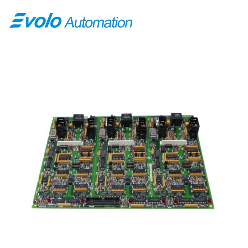
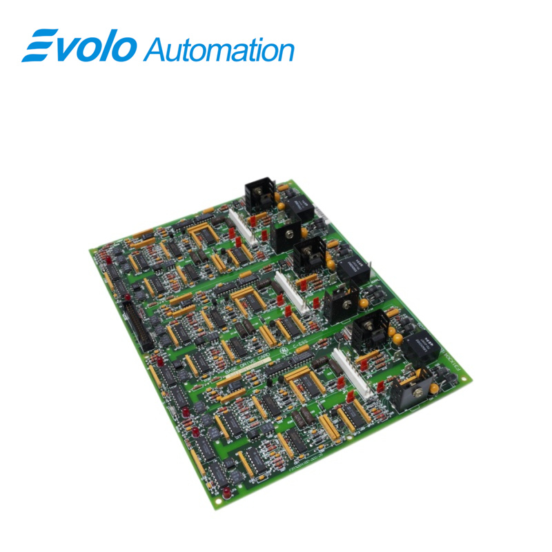
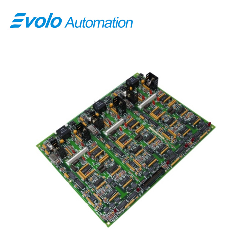
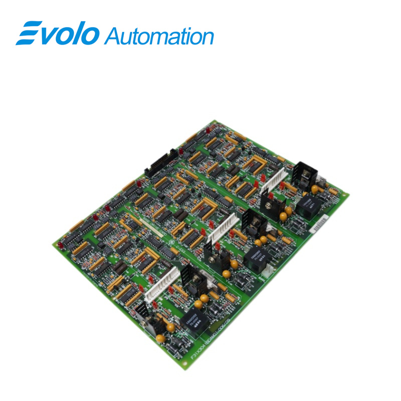
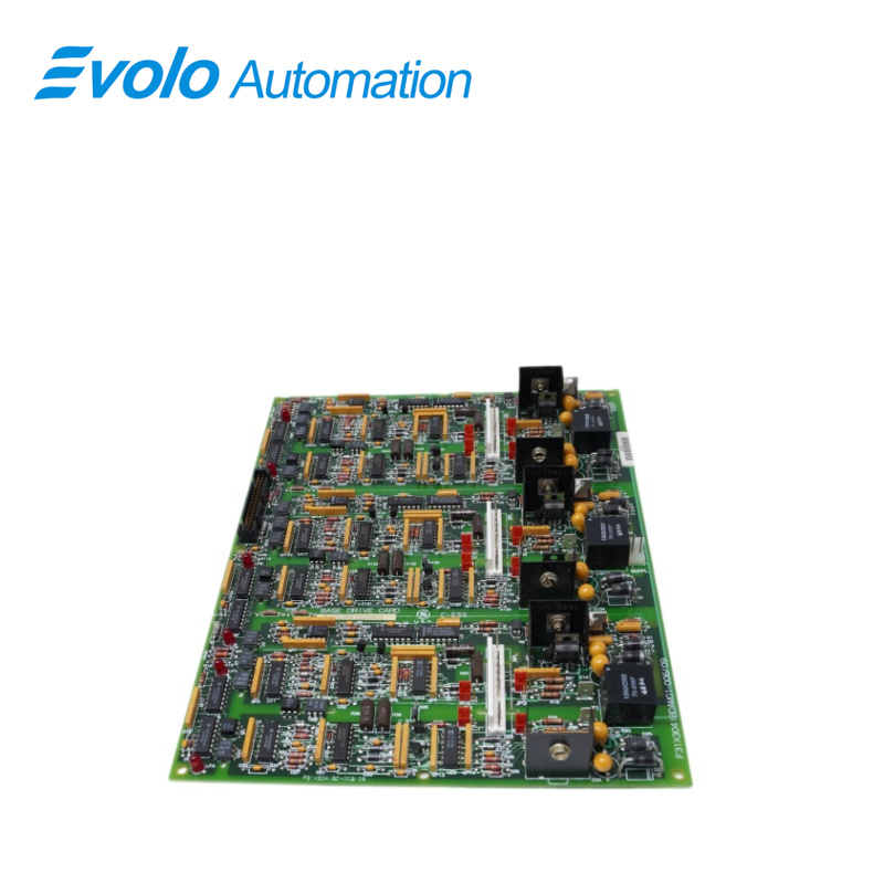
Base Drive Board |
|
Dimensions |
28x21.4x3.4 cm |
|
Weight |
0.52 kg |
|
Connector Type |
Two-pin header connector; vertical pin header connector |
|
LED Indicators |
Six red LED indicators |
|
Components |
Transistor; multiple transistors; two heat sinks; jumper switches; integrated circuits; resistor network arrays; diodes; resistors; capacitors |
|
Input Voltage |
100–240 V AC |
|
Output Voltage |
24 V DC |
|
Output Power |
200 W |
|
Operating Temperature |
-20°C to +60°C |
|
Storage Temperature |
-40°C to +85°C |
Description
The GE Universal Drive System 531X304IBDANG1 F31X304IBDAMG1 is a base drive board suitable for AC-300 and DC-300 series equipment. It provides stable power delivery and efficient drive control, effectively improving system operating efficiency and stability. It is widely used in industrial automation and control systems.
Applications
Steel rolling mill: Provides stable power for control logic and sensor systems in rolling mill drives.
Heavy machinery plant: Uses dual-heatsink drive frames for stable thermal performance during high-frequency machining.
Automated assembly plant: Acts as a distributed power node for multiple actuator systems.
Oil & gas refinery: Integrates into pump control cabinets for stable operation in harsh environments.
Mining plant: Uses interference-resistant electrical control systems for large hoists and heavy equipment.
Maintenance and Troubleshooting
Troubleshooting: If the 6 red LEDs exhibit a specific flashing pattern, first check if the input voltage is within the 100-240V AC range. If the output power decreases, check if dust accumulation on the heatsink surface is affecting the heat dissipation efficiency of the power transistors.
Maintenance Recommendations: Regularly check the tightness of the vertical pin connectors and clean the dual heatsinks to prevent heat buildup. When replacing boards, always verify the physical location of the jump switches to ensure that the logic configuration of the new and old hardware is completely consistent.
FAQ
Q: What do the six red LED indicators on the 531X304IBDANG1 F31X304IBDAMG1 represent?
A: They indicate power status, internal communication activity, and channel alarm signals for quick fault diagnosis.
Q: Does this driver board support automatic switching between 110V and 220V power grids when using the 531X304IBDANG1 F31X304IBDAMG1?
A: Yes. It supports 100–240V AC input with automatic global voltage adaptation.
Q: What are the installation space requirements for the 531X304IBDANG1 F31X304IBDAMG1 dual heatsink design?
A: The 3.4 cm thickness includes the heatsink, and a standard rack slot is sufficient with proper ventilation space.
Q: How do I configure the 531X304IBDANG1 F31X304IBDAMG1 using jumper switches?
A: Jumpers set signal mode or output level; always follow the manual or record original settings before adjustment.