EN
EN




- Overview
- Specifications
- Description
- Applications
- Troubleshooting and Maintenance Recommendations
- FAQ
- Recommended Products
Overview
Place of Origin: |
USA |
Brand Name: |
GE |
Model Number: |
531X135PRGAAM3 |
Packaging Details: |
Original new Factory Sealed |
Delivery Time: |
5-7 days |
Payment Terms: |
T/T |
Supply Ability: |
In stock |
Specifications
|
Part Number |
531X135PRGAAM3 |
|
Product Type |
Programmer Board |
|
Dimensions |
13.8×10.8×1.5 cm |
|
Weight |
0.12 kg |
|
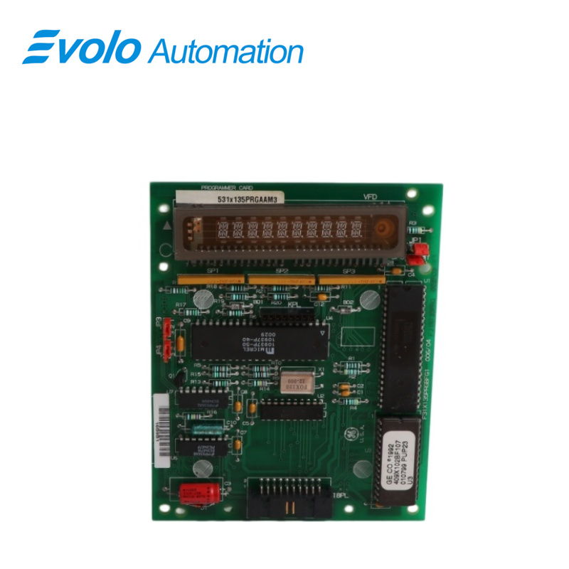
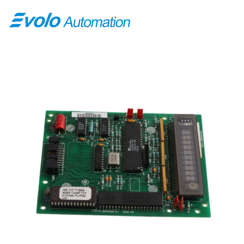
Integrated Circuits |
6 total (EPROM group + EEPROM group) |
|
Capacitors |
13 units (energy storage function) |
|
Resistors |
18 units (current limiting, voltage division, signal adjustment, biasing, termination) |
|
Jumpers |
4 sets (with plastic covers) |
|
Transistor |
1 unit |
|
LED Display |
Large numeric display panel |
|
Functional Purpose |
Controls energy flow routing |
Description
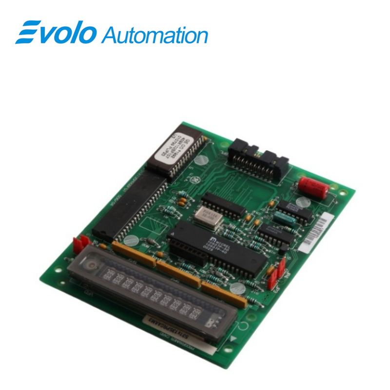
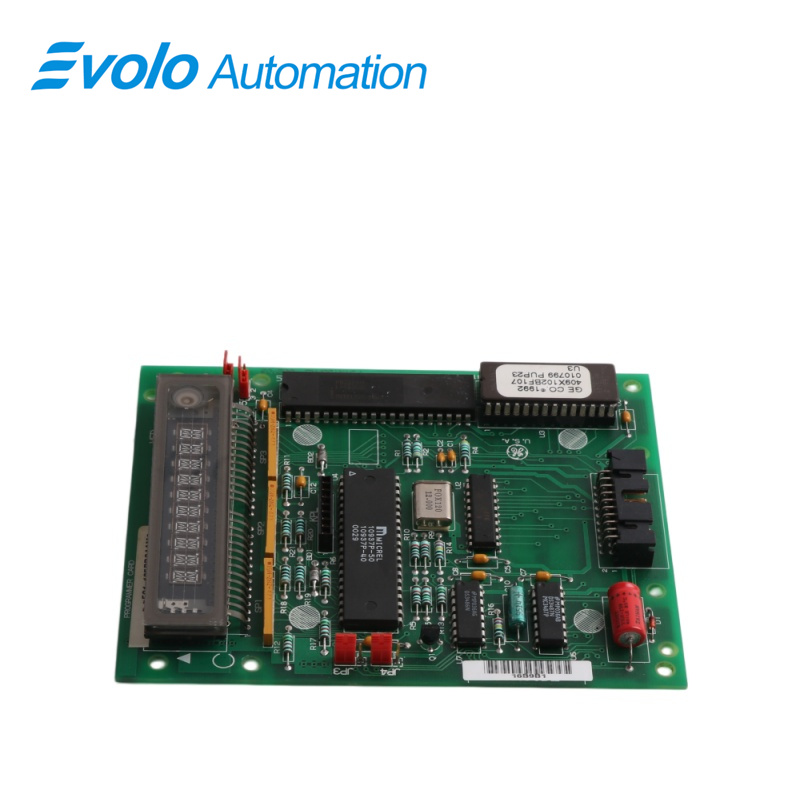
The 531X135PRGAAM3 General Electric Programmer Board is a high-performance component used in GE drive systems. It facilitates programming, configuration, and diagnostics of drive parameters. Featuring advanced microprocessor technology, it ensures precise control and efficient operation in industrial applications.
Applications
Precision strip steel plant: Serving as the programming core in the control cabinet, it utilizes LED panels to provide real-time feedback of rolling logic values, ensuring process visualization.
Smart electronics plant: Used for distributing control commands to automated production lines, leveraging the erasable and rewritable nature of EEPROMs to adapt to program switching between different machine models.
Petrochemical plant: Deployed as a logic monitoring unit in critical compressors, it maintains signal purity in highly interference-prone environments through a precision resistor network.
Paper machinery plant: Widely used for parameter setting in paper machine drive systems, it flexibly adjusts energy paths via jumper ports to match different loads.
Troubleshooting and Maintenance Recommendations
Troubleshooting: If the LED panel displays an error code, first check if the memory chip (EPROM/EEPROM) is loose; use the 4 sets of jumper ports to verify that the energy guiding path matches the current operating conditions.
Maintenance Recommendations: It is recommended to regularly clean the dust from the LED panel and color-ring resistors to prevent resistance drift due to poor heat dissipation; when operating jumper switches, ensure that the original plastic cover is used to prevent accidental short circuits.
FAQ
Q: What is the role of the LED panel on the 531X135PRGAAM3 during operation?
A: It displays system status and fault codes in real time for quick technician reference.
Q: Are the EPROM and EEPROM chipsets on the 531X135PRGAAM3 interchangeable?
A: No. EPROM stores firmware, while EEPROM stores configuration data; both work together for board logic.
Q: How can I adjust circuit logic using the jumper ports on the 531X135PRGAAM3?
A: By repositioning jumper covers to change internal connections and control circuit behavior.
Q: What circuit problems do the 18 sets of color-coded resistors on the 531X135PRGAAM3 address?
A: They handle current limiting, voltage division, signal adjustment, and component biasing.
Q: How does the 531X135PRGAAM3 ensure timing accuracy of program execution?
A: A crystal oscillator provides precise reference frequency for synchronized operation.