EN
EN




- Overview
- Specifications
- Description
- Applications
- Maintenance and Troubleshooting
- FAQ
- Recommended Products
Overview
Place of Origin: |
USA |
Brand Name: |
GE |
Model Number: |
531X179PLMAKG1 |
Packaging Details: |
Original new Factory Sealed |
Delivery Time: |
5-7 days |
Payment Terms: |
T/T |
Supply Ability: |
In stock |
Specifications
|
Product Name |
531X179PLMAKG1 |
|
Type |
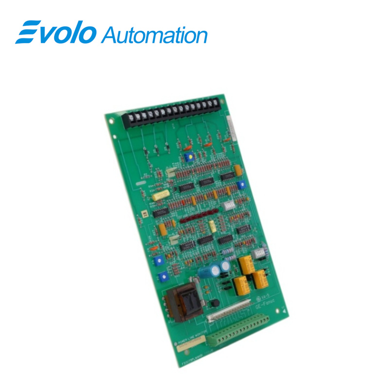
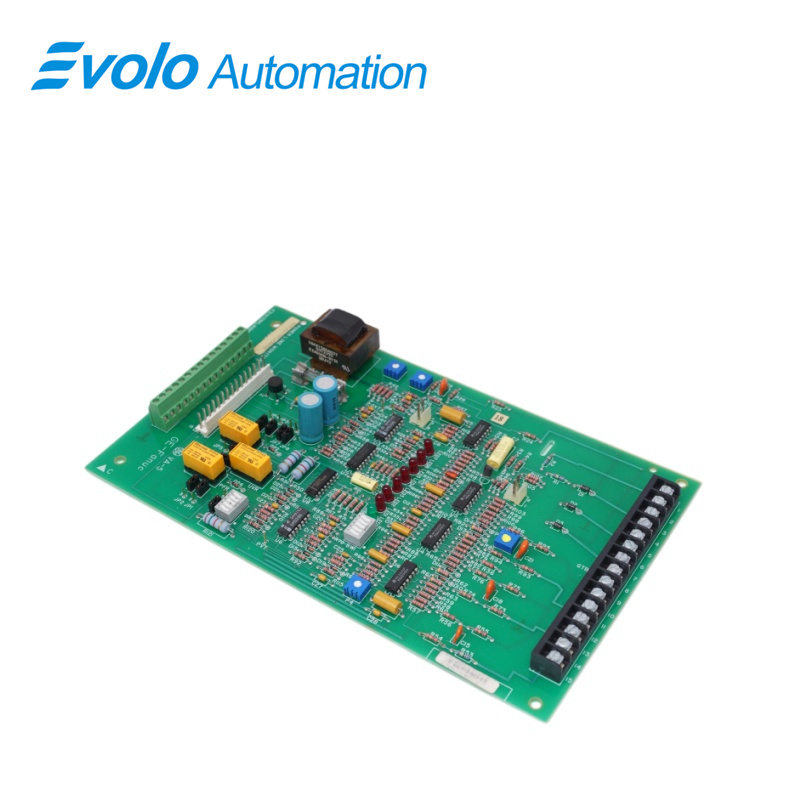
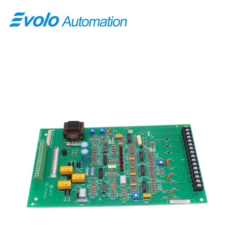
Power Line Monitor |
|
Dimensions |
28x16.5x3.5 cm |
|
Weight |
0.38 kg |
|
LED Indicators |
7 red LEDs; 1 green LED |
|
Display Interface |
Central LED array (7 red LEDs, 1 green LED) |
|
Logic Core |
8 integrated circuits (ICs / microchips) supporting complex logic and data processing |
|
Adjustment Components |
4 blue variable resistors for fine energy adjustment |
|
Safety Protection |
Built-in fuse and multiple diode control arrays |
Description
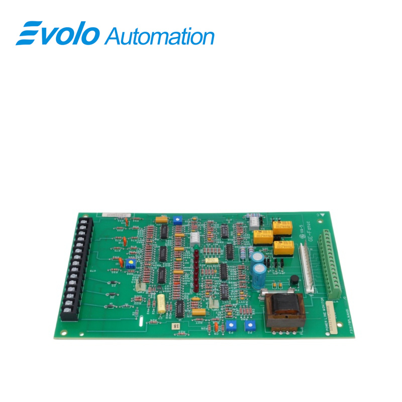
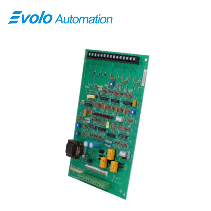
The 531X179PLMAKG1 is a dedicated power line monitor designed by General Electric. This board integrates high-precision monitoring logic, providing real-time feedback on system operating status via an onboard multi-color LED status light array. Its sophisticated design incorporates high-performance integrated circuits (ICs), adjustable resistors, and advanced capacitor arrays, enabling efficient storage and precise regulation of circuit energy.
Applications
Large thermal power plants: Integrated into power distribution monitoring cabinets, providing real-time monitoring of the health status and load fluctuations of critical power lines.
Heavy metal smelting plants: In production workshops with complex electromagnetic environments, LED arrays provide intuitive power fault warnings.
Petrochemical refineries: As a core protection module, monitoring the current flow in automated control systems to prevent backflow damage to sensitive components.
Automotive automated assembly plants: Utilizing onboard chips for precise power logic control in industrial robot power distribution systems.
Paper and printing plants: Deployed on continuously operating production lines, ensuring precise matching of power output and mechanical load through fine-tuning of variable resistors.
Maintenance and Troubleshooting
Troubleshooting: If the system power supply is interrupted, first check if the onboard fuse is blown. If the communication logic is abnormal, the IC module where the fault is located can be quickly identified by the combination pattern of 7 red and 1 green LEDs.
Maintenance Recommendations: It is recommended to regularly check the appearance of the capacitors to prevent the electrolyte from drying out due to long-term operation. Since it integrates 4 sets of variable resistors, manual calibration can be performed when the environmental load changes.
FAQ
Q: What does the lit green LED in the center array of the 531X179PLMAKG1 represent?
A: Indicates normal power operation or standby status, depending on system logic.
Q: How do I adjust the four blue variable resistors on the 531X179PLMAKG1?
A: Use a non-contact screwdriver and fine-tune per system manual for optimal accuracy.
Q: Can the eight IC chips on the 531X179PLMAKG1 be replaced individually?
A: Not recommended; replace the full board if a logic fault occurs.
Q: If the fuse in the 531X179PLMAKG1 blows, is the board damaged?
A: Not necessarily. Replace fuse and check for external shorts first.
Q: What are the advantages of multi-spec capacitors in the 531X179PLMAKG1?
A: They buffer different frequency interference, ensuring stable power quality.