EN




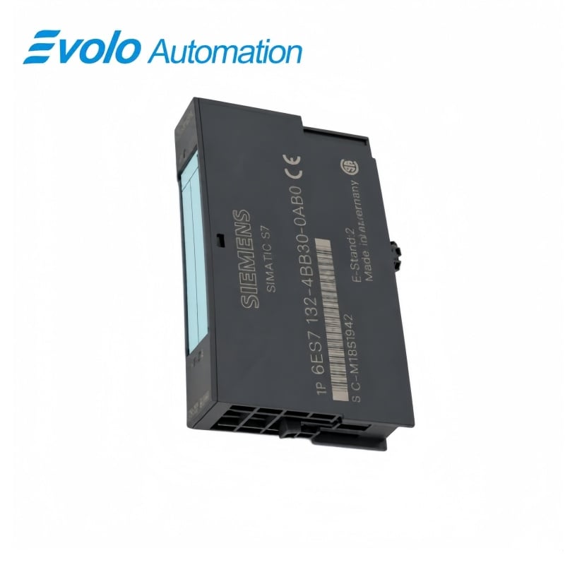
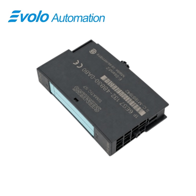
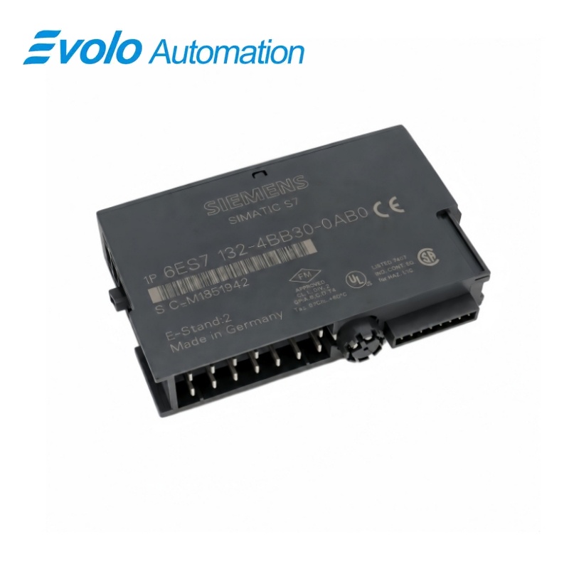
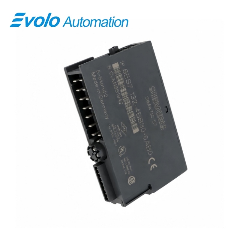
Siemens 6ES7132-4BB30-0AB0 SIMATIC ET 200S 2DO DC24V 2A High Feature Module
Manufacturer: Siemens
Condition: Brand New
Lead Time: In Stock
Origin: Germany
Warranty: 12 Months
Email: [email protected]
whatsApp: +86-18150117685
- Overview
- Hot Selling Models
- Recommended Products
Overview
- Match the two-channel 2 A High Feature article to the station configuration.
- Keep channel current, module total, load resistance and lamp load within the specified limits.
- Use the terminal-base assignment that matches two-, three- or four-wire wiring.
- Connect AUX1 to protective earth in the four-conductor arrangement.
- Allow for the approximately 50 µs signal pulse when switching the load supply mechanically.
- Do not use parallel outputs for uprating; maintain correct polarity and the common load supply with the power module.
6ES7132-4BB30-0AB0 SIMATIC ET 200S 2DO DC24V 2A High Feature Module
A two-channel 24 V DC High Feature module rated at 2 A per output, with clocked-operation support, readable diagnostics and per-channel short-circuit protection.
At a Glance
| Brand | Siemens |
|---|---|
| Model | 6ES7132-4BB30-0AB0 |
| Product Type | High Feature electronic output module |
| Core Function | Switching actuator loads with diagnostic feedback |
| Application | ET 200S digital-output stations |
Two 2 A outputs
The module provides two DC outputs with a 4 A total output rating.
Actuator control
Suitable loads include solenoid valves, DC contactors and indicator lights.
Supply-switching transient
A mechanical supply contact can produce an approximately 50 µs signal-1 pulse, relevant to fast counters.
Product Overview
6ES7132-4BB30-0AB0 provides two 24 V DC High Feature outputs rated at 2 A each for an ET 200S station, with a total module output current of 4 A.
The module supports clocked operation and readable diagnostics, while green channel LEDs and a red SF indicator display local output and group-fault status.
Key Functions
Control the two actuator channels
The outputs switch solenoid valves, DC contactors and indicator lights within the documented current, load-resistance and lamp-load limits.
Protect the output circuit and display faults
Each channel has short-circuit protection with a typical 4 A response threshold, with readable diagnostics and a red SF group-fault indicator.
Support clocked output operation
The module supports clocked operation in a compatible station, with resistive-load output delays up to 100 µs on and 400 µs off.
Official Specifications
| Rated Load Supply | 24 V DC from the power module |
|---|---|
| Output-Current Ratings | 2 channels; 2 A rated each; permitted signal-1 range 7 mA–2.4 A; module total 4 A |
| Minimum Signal-1 Voltage | L+ minus 1 V |
| Maximum Signal-0 Leakage | 0.5 mA |
| Load Resistance Range | 12 Ω–3.4 kΩ |
| Maximum Lamp Load | 5 W |
| Typical Short-Circuit Threshold | 4 A, protected per channel |
| Maximum Resistive-Load Delays | 100 µs off-to-on; 400 µs on-to-off |
| Maximum Switching Frequencies | 100 Hz resistive; 2 Hz inductive with 0.5 H; 10 Hz lamp load |
| Inductive Voltage Limitation | Typically L+ minus 55 to 60 V |
| No-Load Supply Current | Maximum 5 mA per channel from L+ |
| Typical Module Power Dissipation | 1.4 W |
| Permissible Circuit Potential Difference | 75 V DC or 60 V AC |
| Isolation Arrangement and Test | No channel-to-channel isolation; outputs isolated from backplane; 500 V DC test |
| Status and Diagnostic Indication | Green channel LEDs; red SF group LED; readable diagnostics |
| Clocked Operation | Supported in a compatible station |
| Maximum Cable Length | 1000 m shielded; 600 m unshielded |
| Module Dimensions and Approximate Weight | 15 × 81 × 52 mm; 40 g |
Frequently Asked Questions
Why can a fast counter detect a short pulse when I switch the supply to 6ES7132-4BB30-0AB0?
Switching the rated 24 V load supply through a mechanical contact can make the outputs carry signal 1 for approximately 50 µs.
Which loads can I drive from 6ES7132-4BB30-0AB0 within its ratings?
The module is suitable for solenoid valves, DC contactors and indicator lights.
How should AUX1 be connected for four-wire wiring with 6ES7132-4BB30-0AB0?
Apply AUX1 to protective earth when using the four-conductor arrangement.
Can I parallel the two outputs of 6ES7132-4BB30-0AB0 for a load above the channel rating?
Output paralleling is not permitted to increase performance, although redundant triggering within one module is supported.
Can I switch a 10 W indicator lamp with 6ES7132-4BB30-0AB0?
The specified maximum lamp load is 5 W.
What off-state current should I allow for a sensitive load on 6ES7132-4BB30-0AB0?
The maximum leakage current at signal 0 is 0.5 mA.
What minimum current must the energized load draw from 6ES7132-4BB30-0AB0?
The permitted signal-1 current range starts at 7 mA.